

ProductPRODUCT
Featured products
Contact Us
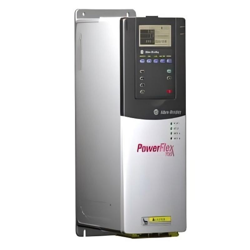
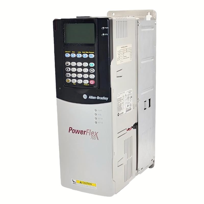
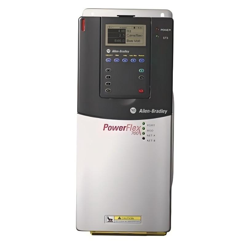
- Allen Bradley
- 20BC022A3AYNAEC1NNAD
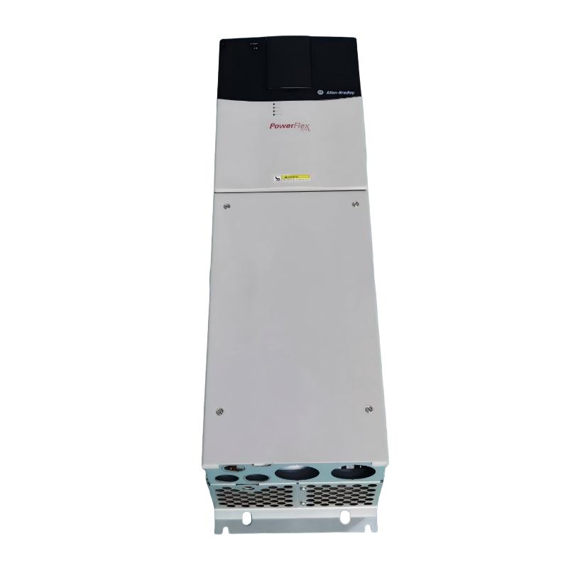
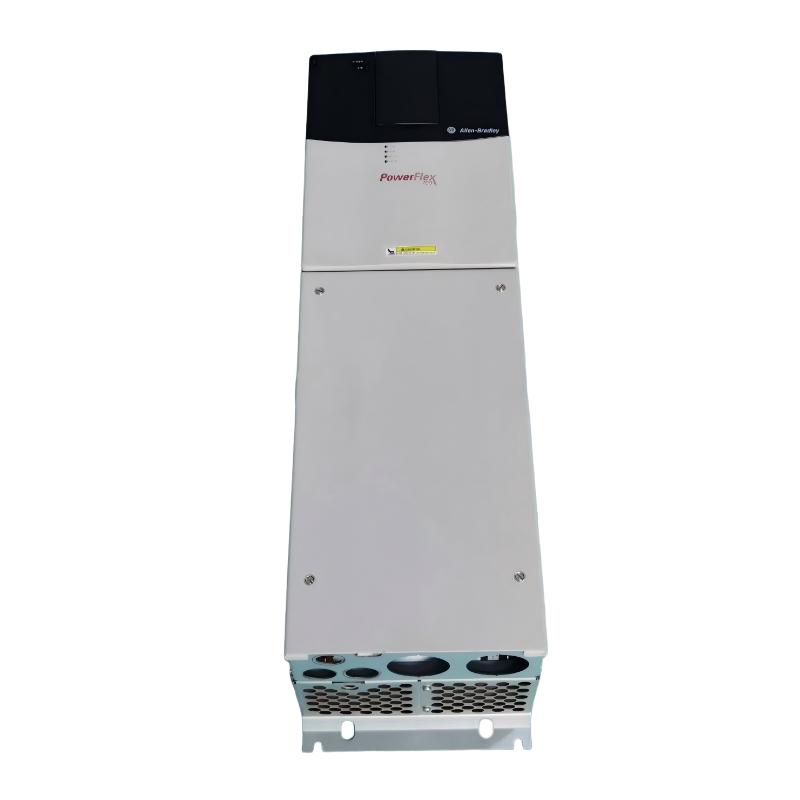
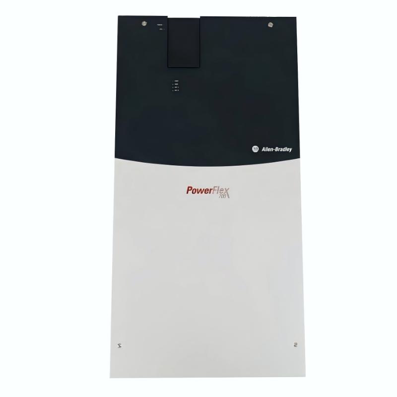
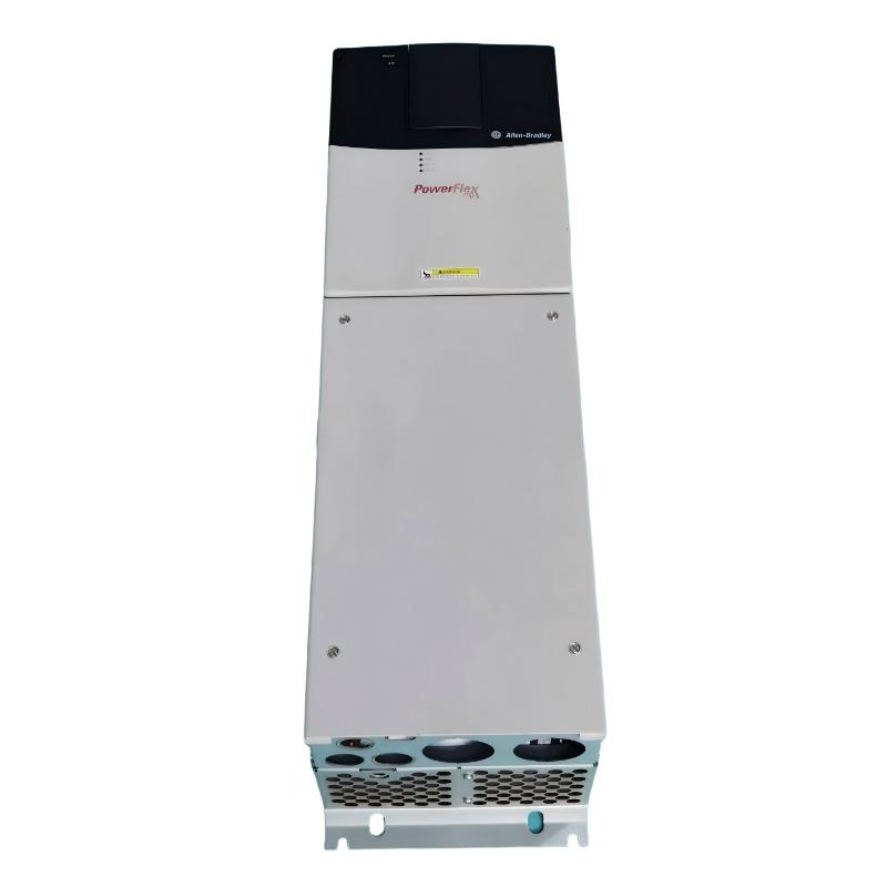
- PowerFlex AC Drive
- USA
- 135 × 336 × 200 mm
- 7.03kg
- Xiamen, China
- New & In Stock
- T/T, PayPal, Western Union
- 1 Year
- 1-3 Working Days
- DHL, UPS, TNT, FedEx and EMS.
- 24-Hour Service
- COO
- 3
Our advantage

Global Logistics
We have a 10-year logistics and express cooperation agreement, so our products can be shipped to any place in the world.

Brand new and original
Our products are imported in bulk from the place of origin. Because of the cooperative relationship, our products are all original and 100% new.

24-hour service
We provide 7*24 hours service to our customers. We will be there whenever you need us.

Price advantage
All our products are priced very favorably because we have our own warehouse and supply.
| Company Information | |||
| [email protected] | |||
| Mobile | +8615980777398 | ||
| +8615980777398 | |||
| 15980777398 |
Allen-Bradley 20BC022A3AYNAEC1NNAD — Product Specifications, Introduction, Applications, Advantages and Related Model Recommendations
1. Product Overview
The 20BC022A3AYNAEC1NNAD is a model designation associated with the PowerFlex 700 series of industrial AC variable-frequency drives. This product family is designed to regulate the speed and torque of compatible AC motors used in industrial machinery, automated production lines, material handling equipment, and process-control systems.
A variable-frequency drive controls motor operation by adjusting the electrical frequency and voltage supplied to the motor. This allows machinery to operate at different speeds, follow controlled acceleration and deceleration profiles, and respond to changing production requirements.
The PowerFlex 700 family is intended for industrial applications requiring adjustable motor speed, flexible control arrangements, and integration with automation equipment. Depending on the exact drive configuration, available features may include vector control, programmable control inputs and outputs, communication options, motor feedback, and braking-related functions.
The complete model number is important because each character group can identify a particular electrical rating or hardware configuration. The precise voltage class, output current, motor power rating, enclosure, braking options, communication interfaces, dimensions, and weight must be confirmed for the exact unit before it is specified for purchase or replacement.
This technical profile is structured for industrial product catalogues, procurement documentation, maintenance planning, and preliminary engineering evaluation. Where the exact specification cannot be established confidently from the model designation alone, the corresponding value is identified as requiring confirmation rather than presented as a guaranteed rating.
2. Brand and Product Series
|
Item |
Product information |
|---|---|
|
Brand |
Allen-Bradley |
|
Model |
|
|
Product family |
PowerFlex 700 |
|
Product category |
Adjustable-frequency AC drive |
|
Main function |
Variable-speed control of compatible AC motors |
|
Nominal voltage class |
400 V AC |
|
Supply configuration |
Three-phase |
|
Rated output current |
22 A |
|
Normal-duty motor rating |
Approximately 11 kW |
|
Heavy-duty motor rating |
Approximately 7.5 kW |
|
Frame size |
Frame 1, subject to confirmation of the complete configuration |
|
Enclosure |
IP20 / NEMA Type 1 configuration, subject to suffix verification |
|
Control method |
Vector-control drive family |
|
Control I/O |
Configuration-dependent |
|
Communication interface |
Requires confirmation of the installed options |
|
Braking capability |
Requires confirmation of the exact configuration |
|
Dimensions |
Approximately 135 × 336 × 200 mm for the corresponding Frame 1 enclosure |
|
Drive weight (kg) |
Approximately 7.03 kg for the corresponding Frame 1 drive |
|
Packaged weight (kg) |
Approximately 9.98 kg for the corresponding Frame 1 configuration |
|
Product status |
Exact lifecycle status should be confirmed for this complete catalog number |
The PowerFlex 700 family is designed for industrial motor-control applications that need adjustable operating speed, controlled acceleration, and integration with machinery control systems.
The 20BC022A3AYNAEC1NNAD designation is closely related to the 20BC022A3AYNANC0 configuration. However, the additional characters in the supplied model number may represent specific hardware or option differences. The ratings and dimensions above are therefore a preliminary reference based on the corresponding 22 A, 400 V, Frame 1 configuration, not a guarantee that every suffix option is identical.
For purchasing or replacement purposes, the full nameplate and configuration record should be checked before treating these figures as final specifications.
3. Detailed Technical Specifications
3.1 Electrical Parameters
The 20BC022A3AYNAEC1NNAD belongs to the 400 V class of industrial AC drives, based on its model designation. The corresponding 22 A PowerFlex 700 configuration is typically associated with an 11 kW normal-duty rating and a 7.5 kW heavy-duty rating.
These two power ratings represent different loading conditions. Normal-duty applications generally allow a higher motor power rating, while heavy-duty applications require additional overload capability for demanding torque profiles.
|
Parameter |
Specification |
|---|---|
|
Model |
20BC022A3AYNAEC1NNAD |
|
Product series |
PowerFlex 700 |
|
Input voltage class |
400 V AC |
|
Nominal supply |
Three-phase AC |
|
Supply frequency |
Typically 50/60 Hz; confirm the exact configuration |
|
Rated output current |
22 A |
|
Normal-duty motor rating |
Approximately 11 kW |
|
Heavy-duty motor rating |
Approximately 7.5 kW |
|
Normal-duty horsepower equivalent |
Approximately 15 HP |
|
Heavy-duty horsepower equivalent |
Approximately 10 HP |
|
Output phases |
Three-phase |
|
Output frequency range |
Depends on the configured operating parameters and applicable drive limits |
|
Control technology |
Vector-control drive family |
|
Motor control |
Adjustable speed and torque control within the supported operating modes |
|
Overload capability |
Must be confirmed for the selected duty rating |
|
Control input voltage |
Configuration-dependent |
|
Digital and analog I/O |
Confirm the installed control-board configuration |
|
Motor feedback |
Confirm the installed feedback options |
|
Communication interface |
Confirm the complete model suffix |
|
EMC filtering |
Confirm the installed filter configuration |
|
Braking hardware |
Confirm whether a braking IGBT or external braking arrangement is required |
|
Motor thermal protection |
Requires correct motor data and appropriate protection settings |
|
Short-circuit protection |
External protective devices must be selected according to the installation requirements |
3.2 Mechanical Parameters
|
Parameter |
Specification |
|---|---|
|
Model |
20BC022A3AYNAEC1NNAD |
|
Frame size |
Frame 1, provisionally identified |
|
Enclosure category |
IP20 / NEMA Type 1, subject to confirmation |
|
Width (mm) |
Approximately 135 mm |
|
Height (mm) |
Approximately 336 mm |
|
Depth (mm) |
Approximately 200 mm |
|
Overall dimensions (W × H × D) |
Approximately 135 × 336 × 200 mm |
|
Mounting bracket hole width (mm) |
Approximately 105 mm |
|
Mounting bracket hole height (mm) |
Approximately 320 mm |
|
Net drive weight (kg) |
Approximately 7.03 kg |
|
Packaged weight (kg) |
Approximately 9.98 kg |
|
Installation method |
Panel mounting according to the applicable installation drawing |
|
Cooling arrangement |
Follow the specified ventilation and mounting-clearance requirements |
|
Mounting orientation |
Confirm the permitted orientation in the installation instructions |
|
Environmental protection |
Appropriate for the specified enclosure and installation environment |
|
Service clearance |
Allow space for ventilation, wiring, and maintenance |
The dimensions above are reference values for the corresponding Frame 1 drive configuration. They should be checked against the mechanical drawing for the complete catalog number before panel fabrication or replacement work.
Net drive weight and packaged weight are different measurements. The former is used for equipment mounting calculations, while the latter is relevant to shipping and handling.
3.3 Operating and Environmental Parameters
|
Parameter |
Description |
|---|---|
|
Ambient operating temperature |
Depends on the drive configuration; derating may be necessary at elevated temperatures |
|
Relative humidity |
Use within the specified non-condensing humidity range |
|
Installation altitude |
Confirm the maximum permitted altitude and derating requirements |
|
Pollution degree |
Must match the installation environment and enclosure protection |
|
Electrical noise management |
Follow the specified grounding, bonding, cable-routing, and filtering requirements |
|
Motor cable |
Select according to voltage, current, length, and applicable installation requirements |
|
Cabinet ventilation |
Must be sufficient to dissipate drive losses |
|
Maintenance access |
Provide access to terminals, cooling passages, and serviceable components |
|
Storage conditions |
Follow the applicable product installation and maintenance instructions |
Environmental conditions affect drive reliability and service life. High ambient temperature, poor ventilation, contamination, and excessive electrical noise can all contribute to operating problems.
The drive should be installed in an enclosure and environment appropriate to its protection rating. IP20 equipment should not be exposed directly to water or other conditions beyond its specified environmental limits.
4. Product Introduction
The PowerFlex 700 is an industrial adjustable-frequency AC drive designed to control the operating characteristics of compatible motors. It allows the motor speed to be adjusted in response to production requirements rather than remaining fixed at the speed associated with the electrical supply.
The 20BC022A3AYNAEC1NNAD is relevant to machinery that requires a drive in the approximate 11 kW normal-duty power class or the corresponding heavy-duty rating, subject to verification of the complete configuration.
4.1 Variable-Speed Motor Control
The drive adjusts the frequency and voltage supplied to a compatible AC motor. This enables operators or automation controllers to regulate machine speed according to process demand.
For example, a conveyor may run slowly while products are being positioned and increase speed during normal transportation. A pump may operate at different speeds according to flow requirements, while a mixer may follow a programmed speed profile throughout a production cycle.
4.2 Controlled Acceleration and Deceleration
The drive can be configured with acceleration and deceleration ramps to control how quickly the motor changes speed.
A controlled ramp can help reduce sudden mechanical loading on shafts, couplings, belts, and gearboxes. It can also make machine operation more consistent when repeated starts and stops are required.
The correct ramp settings depend on the motor, load inertia, production cycle, and stopping requirements.
4.3 Vector-Control Capability
Vector-control technology allows the drive to regulate motor operation more effectively than simple frequency adjustment in applications that require improved torque response and speed control.
Actual performance depends on the selected operating mode, motor parameters, drive configuration, and any installed feedback options. Closed-loop performance should not be assumed unless the required feedback hardware is present.
4.4 Integration with Industrial Machinery
A variable-frequency drive is normally installed as part of a wider electrical and automation system.
The system may include a programmable controller, operator interface, sensors, contactors, protective devices, and communication interfaces. The exact model configuration determines which control and communication functions are available directly and which require additional hardware.
4.5 Suitability for Industrial Duty
The 22 A rating provides a useful starting point for evaluating motors in the relevant power range. However, rated current, overload requirements, motor voltage, ambient temperature, and operating cycle must all be considered when determining suitability.
A drive should never be selected solely because its nominal kilowatt rating appears to match the motor.
5. Product Applications

5.1 Conveyor and Material Handling Systems
Conveyors transport products and raw materials between production stages, packaging stations, storage areas, and processing equipment.
Variable-speed control enables the operator to adjust conveyor speed to suit the production rate. Controlled acceleration can also reduce mechanical shock during starting and stopping.
The drive must be selected according to conveyor load, belt speed, motor current, and the required acceleration profile.

5.2 Industrial Pumping Systems
Pumps are used in water circulation, industrial processing, cooling systems, and liquid transfer applications.
A variable-frequency drive can adjust pump speed to meet changing flow or pressure requirements. In suitable centrifugal pump systems, speed control may reduce energy consumption compared with continuously operating at full speed.
Engineers should evaluate the pump curve, minimum speed, motor cooling, and required flow range before selecting the drive.

5.3 Fans and Ventilation Equipment
Industrial fans often operate under changing ventilation or airflow requirements.
The drive can regulate fan speed to match actual demand and help avoid unnecessary full-speed operation. The potential energy benefit depends on fan characteristics, duct resistance, and operating schedules.
Correct drive sizing should account for motor current, acceleration requirements, and the fan’s operating range.

5.4 Mixers and Agitators
Industrial mixers may require different speeds during loading, blending, and discharge.
A variable-frequency drive can provide adjustable speed and controlled acceleration, allowing the process to follow a defined operating sequence.
Applications involving viscous materials or frequent changes in load torque require careful assessment of motor current and overload capacity.

5.5 General Industrial Processing Machinery
Many production machines use AC motors to power rollers, auxiliary drives, feeders, and mechanical processing units.
Speed regulation can help coordinate production stages and allow operators to adapt the machine to different operating conditions.
The drive is suitable only where the motor and application requirements fall within its verified electrical and thermal ratings.
5.6 Additional Application Areas
Other potential applications for appropriately sized drives in this family include:
-
Industrial ventilation and air-handling systems.
-
Water treatment and circulation equipment.
-
Packaging and converting machinery.
-
Production-line transport systems.
-
Industrial agitators and process mixers.
-
General manufacturing equipment.
-
Auxiliary machinery in automated production facilities.
-
Compatible material-feeding and processing systems.
These examples describe application categories rather than a guarantee of compatibility with every machine. Applications involving hoists, cranes, elevators, or suspended loads require additional assessment of braking, load control, and safety requirements.
6. Product Advantages
6.1 Adjustable Operating Speed
A variable-frequency drive allows motor speed to be matched to the process rather than relying on a fixed-speed arrangement.
This can improve operational flexibility when production rates change or when different products require different machine speeds.
6.2 Controlled Starting and Stopping
Programmable acceleration and deceleration can reduce sudden changes in torque and mechanical loading.
This can help protect belts, couplings, shafts, and other transmission components when the drive is configured appropriately.
6.3 Improved Process Control
Adjustable motor speed makes it easier to coordinate machinery with sensors, process controllers, and other production equipment.
In a properly designed system, the drive can support more consistent operation and reduce the need for mechanical speed adjustment.
6.4 Vector-Control Technology
The PowerFlex 700 family provides vector-control capabilities for applications requiring more responsive motor control.
The available performance depends on the exact drive configuration, motor data, and selected control mode.
6.5 Flexible Industrial Integration
Depending on the installed hardware, the drive can be integrated into a broader industrial automation system using suitable I/O and communication options.
The complete suffix must be checked before assuming that a particular network interface, feedback feature, or operator interface is present.
6.6 Potential Energy Savings
In suitable variable-load applications, reducing motor speed can reduce power consumption.
This is particularly relevant to certain fan and centrifugal pump systems. The actual energy savings depend on the application, the load profile, motor efficiency, and the amount of time spent operating at reduced speed.
6.7 Maintenance and Fault Diagnosis
A configured drive can provide operating status and fault information that helps maintenance personnel investigate electrical, motor, or load-related problems.
The information available depends on the drive hardware, configuration, and connected control system.
6.8 Suitability for Existing Industrial Installations
When a compatible PowerFlex 700 configuration is already installed, retaining the same drive family may simplify some aspects of maintenance and integration.
However, a replacement should still be checked for electrical ratings, control I/O, communication interfaces, mounting dimensions, and braking requirements.
7. Five Related Models in the PowerFlex 700 Series
The following five models are related PowerFlex 700 configurations. The first is the reference model, and the remaining entries are alternatives for comparison.
These models are not guaranteed direct replacements. Different suffixes may identify changes in control hardware, operator interface, communication options, or braking arrangements.
|
No. |
Model |
Series |
Voltage and current |
Motor power rating |
Dimensions (mm) |
Weight (kg) |
|---|---|---|---|---|---|---|
|
1 |
20BC022A3AYNAEC1NNAD |
PowerFlex 700 |
400 V class, 22 A; confirm complete suffix |
Approx. 11 kW normal duty / 7.5 kW heavy duty |
Approx. 135 × 336 × 200 |
Approx. 7.03 net |
|
2 |
20BC022A3AYNANC0 |
PowerFlex 700 |
400 V class, 22 A |
Approx. 11 kW normal duty / 7.5 kW heavy duty |
Approx. 135 × 336 × 200 |
Approx. 7.03 net |
|
3 |
20BC022A3AYNACC0 |
PowerFlex 700 |
400 V class, 22 A |
Approx. 11 kW normal duty / 7.5 kW heavy duty |
Approx. 135 × 336 × 200 |
Approx. 7.03 net |
|
4 |
20BC015A3AYNANC0 |
PowerFlex 700 |
400 V class; verify exact current rating |
Model-specific |
Model-specific |
Not verified |
|
5 |
20BC030A3AYNANC0 |
PowerFlex 700 |
400 V class; verify exact current rating |
Model-specific |
Model-specific |
Not verified |
The 22 A models provide useful starting points for comparing drives with similar nominal current and power ratings. Nevertheless, their suffixes may represent materially different configurations.
The 15 A and 30 A entries represent alternative rating classes, not interchangeable replacements. A higher-current drive is not automatically the best choice, and a lower-current model may be unsuitable for the existing motor.
For purchasing purposes, the full model number and installed options must be verified before selecting any of these alternatives.
8. Five Other Allen-Bradley Models Worth Considering
The following models belong to the broader PowerFlex drive range. They are included as alternatives for different motor sizes and control requirements, not as direct replacements for the 22 A PowerFlex 700.
|
No. |
Model |
Product family |
General electrical specification |
Dimensions (mm) |
Weight (kg) |
|---|---|---|---|---|---|
|
1 |
25B-D2P3N104 |
PowerFlex 525 |
480 V class; small-motor drive, approximately 1 HP class |
Model-specific; verify drawing |
Not verified |
|
2 |
25B-D6P0N104 |
PowerFlex 525 |
480 V class; approximately 3 HP class |
Model-specific; verify drawing |
Not verified |
|
3 |
25B-D010N104 |
PowerFlex 525 |
480 V class; approximately 5 HP class |
Model-specific; verify drawing |
Not verified |
|
4 |
25B-D013N104 |
PowerFlex 525 |
480 V class; approximately 7.5 HP class |
Model-specific; verify drawing |
Not verified |
|
5 |
25B-D017N104 |
PowerFlex 525 |
480 V class; approximately 10 HP class |
Model-specific; verify drawing |
Not verified |
These PowerFlex 525 models serve different power ranges from the reference drive. Their suitability depends on the motor voltage, current, overload requirements, and application.
The physical dimensions and weights are intentionally marked for verification rather than estimated, because different frames and hardware revisions may have different mechanical specifications.
9. Comparative Selection Guide
|
Selection criterion |
Reference model |
Related PowerFlex 700 |
PowerFlex 525 alternatives |
|---|---|---|---|
|
Main function |
Industrial AC motor speed control |
Industrial AC motor speed control |
Compact AC motor speed control |
|
Voltage class |
400 V |
Depends on model |
Model-dependent; listed examples are 480 V class |
|
Output current |
Approximately 22 A |
Must be verified |
Lower current ratings for the listed examples |
|
Normal-duty power |
Approximately 11 kW |
Model-dependent |
Smaller motor power range |
|
Heavy-duty power |
Approximately 7.5 kW |
Model-dependent |
Model-specific |
|
Vector-control capability |
Family-level capability; verify configuration |
Verify configuration |
Verify individual model capabilities |
|
Communication options |
Confirm suffix |
Confirm suffix |
Confirm model and options |
|
Feedback options |
Confirm suffix |
Confirm suffix |
Confirm model and options |
|
Braking configuration |
Confirm suffix |
Confirm suffix |
Confirm model and options |
|
Dimensions (mm) |
Approx. 135 × 336 × 200 |
Model-dependent |
Model-dependent |
|
Weight (kg) |
Approx. 7.03 net |
Model-dependent |
Model-dependent |
|
Direct replacement suitability |
Original reference |
Requires engineering verification |
Generally not a direct replacement at this power rating |
9.1 Motor and Drive Matching
The motor’s rated current is one of the most important selection parameters. The drive must supply sufficient current under the intended operating conditions without exceeding its thermal or overload limits.
Motor power is also important, but horsepower or kilowatt ratings alone do not establish compatibility. Voltage, power factor, motor efficiency, torque requirements, and operating duty must be taken into account.
9.2 Mechanical Compatibility
When replacing an existing drive, compare the overall dimensions, mounting-hole locations, terminal access, cable entry, and ventilation clearances.
A drive with similar electrical ratings may have a different frame size or mounting arrangement. Cabinet modifications may therefore be necessary even when the motor-control function is similar.
9.3 Control and Communication Compatibility
The existing PLC, operator interface, and field wiring may depend on specific drive I/O or communication options.
Before choosing a replacement, identify how speed commands, start/stop signals, fault status, and any additional process information are exchanged between the drive and the machine controller.
9.4 Braking and Stopping Requirements
Some loads require dynamic braking to control deceleration or manage energy returned by the motor during stopping.
The braking hardware fitted to the reference model must be identified before selecting an alternative. If the application requires braking capability, confirm the need for an internal braking transistor, an external resistor, or another engineered arrangement.
Safety-related stopping requirements should be assessed separately from ordinary motor speed control.
10. Installation and Maintenance Recommendations
10.1 Electrical Installation
The drive should be installed by qualified personnel using the applicable electrical drawings and installation instructions.
Verify the supply voltage, phase configuration, grounding, protective devices, conductor sizes, motor-cable requirements, and short-circuit ratings before energizing the equipment.
10.2 Mechanical Installation
Ensure that the mounting surface is suitable for the drive’s weight and that the panel provides sufficient ventilation and maintenance access.
Use the exact mechanical drawing to confirm the mounting-hole positions and overall clearance before drilling or modifying a cabinet.
10.3 Parameter Setup
Before starting the motor, enter the correct motor nameplate data and configure the drive’s control mode, acceleration and deceleration ramps, current limits, and applicable protection settings.
Incorrect parameters can result in poor speed regulation, overcurrent trips, overheating, or unexpected machine behaviour.
10.4 Routine Inspection
A preventive maintenance plan should include inspection of electrical connections, grounding, ventilation passages, cooling components, wiring insulation, and signs of contamination.
The maintenance interval should reflect the installation environment, operating hours, thermal conditions, and the relevant maintenance instructions.
10.5 Replacement Planning
When the exact model is difficult to obtain, evaluate the full cost of retaining the existing drive against replacing it with a compatible alternative.
Replacement planning should include electrical assessment, panel modifications, control-system changes, parameter migration, commissioning, and production testing.
11. Final Product Summary
The 20BC022A3AYNAEC1NNAD is associated with the PowerFlex 700 industrial AC drive family. Based on its related 22 A configuration, the preliminary reference ratings are 400 V class, approximately 11 kW normal duty, and approximately 7.5 kW heavy duty.
The corresponding Frame 1 reference dimensions are approximately 135 × 336 × 200 mm, with a net drive weight of approximately 7.03 kg and a packaged weight of approximately 9.98 kg.
The PowerFlex 700 family is intended for adjustable-speed industrial motor applications, including conveyors, pumps, fans, mixers, and general production machinery. Its practical advantages include adjustable speed, controlled acceleration and deceleration, vector-control capability, and integration into industrial control systems.
The most important consideration is the complete model suffix. It may identify options that affect control I/O, communication, braking, or other operating features. Consequently, the related PowerFlex 700 models listed above should be treated as candidates for engineering comparison rather than guaranteed drop-in replacements.
Specification note: The electrical ratings and mechanical values in this document are preliminary references for the corresponding 22 A, 400 V, Frame 1 configuration. The exact dimensions, weight, hardware options, and operating ratings of the complete 20BC022A3AYNAEC1NNAD model should be confirmed from its nameplate and configuration documentation before purchasing, installation, or replacement.