

ProductPRODUCT
Featured products
Contact Us
- Allen Bradley
- 20BB192A0ANNANC0
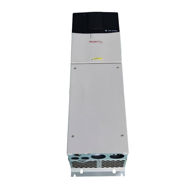
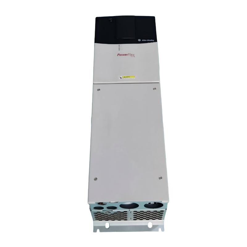
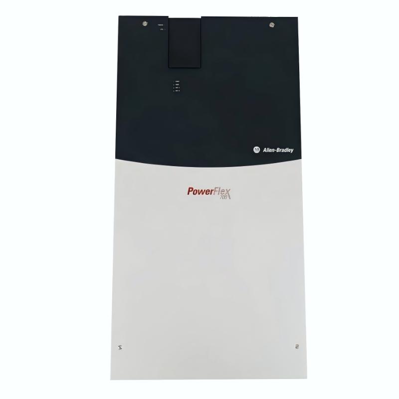
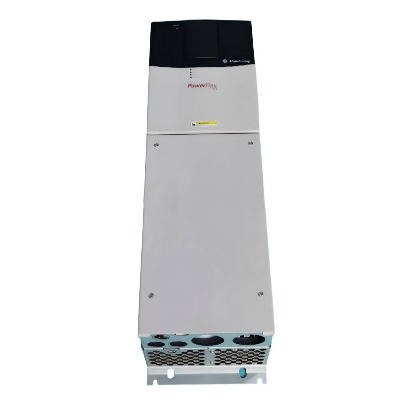
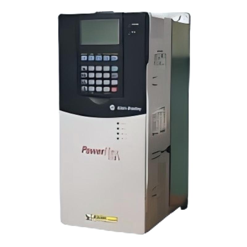
- PowerFlex AC Drive
- USA
- 403.9 × 850.0 × 275.5 mm
- 71.44kg
- Xiamen, China
- New & In Stock
- T/T, PayPal, Western Union
- 1 Year
- 1-3 Working Days
- DHL, UPS, TNT, FedEx and EMS.
- 24-Hour Service
- COO
- 4
Our advantage

Global Logistics
We have a 10-year logistics and express cooperation agreement, so our products can be shipped to any place in the world.

Brand new and original
Our products are imported in bulk from the place of origin. Because of the cooperative relationship, our products are all original and 100% new.

24-hour service
We provide 7*24 hours service to our customers. We will be there whenever you need us.

Price advantage
All our products are priced very favorably because we have our own warehouse and supply.
| Company Information | |||
| [email protected] | |||
| Mobile | +8615980777398 | ||
| +8615980777398 | |||
| 15980777398 |
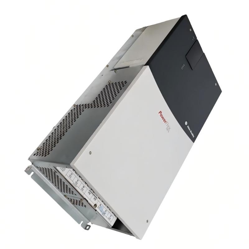
Allen-Bradley 20BB192A0ANNANC0 — Product Specifications, Technical Overview, Applications, Advantages and Related Models
1. Product Overview
The 20BB192A0ANNANC0 is a model designation associated with the PowerFlex 700 series of industrial AC variable-frequency drives. This equipment category is designed to control the speed and torque of AC motors in industrial machinery, production lines, material handling systems, and other automated applications.
A variable-frequency drive (VFD) regulates the electrical power supplied to a motor, allowing the motor to operate at different speeds according to the machine’s requirements. Compared with operating a motor directly from a fixed-frequency supply, a correctly selected drive can provide controlled acceleration, deceleration, adjustable operating speed, and improved coordination with the wider automation system.
The PowerFlex 700 family is intended for industrial applications that require flexible motor control and integration with automation equipment. Depending on the exact drive configuration, the product family supports a range of control functions, protection features, and communication options.
The complete model number is important because PowerFlex drives are supplied in different power ratings, voltage classes, enclosure configurations, filtering arrangements, and option combinations. The precise electrical ratings and physical specifications of 20BB192A0ANNANC0 should therefore be confirmed against the corresponding nameplate and product configuration.
This document is intended for technical catalogues, purchasing descriptions, equipment maintenance records, and preliminary engineering assessment. Unverified model-specific figures are identified as such rather than presented as guaranteed ratings.
2. Brand and Product Series
|
Item |
Technical information |
|---|---|
|
Brand |
Allen-Bradley |
|
Model |
20BB192A0ANNANC0 |
|
Product name |
PowerFlex 700 AC Drive |
|
Product series |
PowerFlex 700 |
|
Product category |
Industrial AC variable-frequency drive |
|
Drive voltage class |
200–240 V AC |
|
Nominal supply voltage |
240 V AC |
|
Input phases |
Three-phase |
|
Output phases |
Three-phase |
|
Rated output current |
192 A |
|
Normal-duty motor rating |
75 HP, approximately 55.9 kW |
|
Heavy-duty motor rating |
60 HP, approximately 44.7 kW |
|
Maximum output frequency |
420 Hz |
|
Enclosure rating |
IP20 / NEMA Type 1 |
|
Control method |
Vector control |
|
Control I/O |
24 V I/O |
|
Operator interface |
No HIM; blank plate configuration |
|
Dynamic braking IGBT |
Not included |
|
Drive-mounted braking resistor |
Not included |
|
EMC filter |
Included |
|
Communication module |
Not included in the specified configuration |
|
Motor feedback option |
No feedback option |
|
Approximate dimensions (W × H × D) |
403.9 × 850.0 × 275.5 mm, including mounting hardware |
|
Approximate drive weight (kg) |
71.44 kg |
|
Product lifecycle |
Discontinued |
|
Replacement approach |
Engineering assessment and compatible replacement selection required |
The PowerFlex 700 is an industrial drive family intended for applications that need adjustable AC motor speed, controlled acceleration and deceleration, and flexible integration with machine control systems.
The exact suffix of the model number identifies important configuration details. For this unit, the absence of a communication module, the 24 V I/O arrangement, the absence of motor feedback, and the lack of an integrated braking IGBT should all be considered when planning a replacement.
The specified model has been discontinued. A replacement should therefore be selected based on the original machine requirements, electrical ratings, enclosure, control interface, and installation dimensions rather than model name alone.
3. Detailed Technical Specifications
3.1 Electrical Parameters
The 20BB192A0ANNANC0 is designed for industrial three-phase AC motor control. Its 192 A output-current rating and 75 HP normal-duty rating place it in the higher-power range of conventional industrial variable-frequency drives.
|
Parameter |
Specification |
|---|---|
|
Model |
20BB192A0ANNANC0 |
|
Input voltage range |
200–240 V AC drive class |
|
Nominal input voltage |
240 V AC |
|
Input phase |
3-phase |
|
Output phase |
3-phase |
|
Rated output current |
192 A |
|
Normal-duty motor rating |
75 HP / approximately 55.9 kW |
|
Heavy-duty motor rating |
60 HP / approximately 44.7 kW |
|
Maximum output frequency |
420 Hz |
|
Nominal supply frequency |
60 Hz configuration |
|
Input frequency tolerance |
47 Hz minimum specified tolerance point; confirm operating limits in the applicable technical manual |
|
Nominal efficiency |
Approximately 97.5% at rated current and nominal line voltage |
|
Vector control |
Supported |
|
Analog inputs |
2 |
|
Analog outputs |
2 |
|
Digital inputs |
6 |
|
Digital outputs |
3 |
|
Control I/O voltage |
24 V |
|
Motor feedback |
Not included in the specified configuration |
|
Dynamic braking IGBT |
Not included |
|
Integrated braking resistor |
Not included |
|
Communication module |
Not installed in the specified configuration |
|
EMC filter |
Included |
|
Conformal coating |
Included |
|
Output frequency setting |
Application-dependent, up to the specified maximum |
|
Overload capacity |
Must be confirmed against the applicable duty rating and manual |
Important rating distinction: Normal-duty and heavy-duty ratings describe different motor loading requirements. The 75 HP normal-duty rating should not be assumed to apply to every constant-torque or high-overload application. For demanding loads, the 60 HP heavy-duty rating is the more relevant starting point, subject to verification of the actual load profile.
The motor’s current requirements, starting torque, overload duration, acceleration time, and operating environment must all be evaluated before selecting the drive.
3.2 Physical and Mechanical Parameters
|
Parameter |
Specification |
|---|---|
|
Model |
20BB192A0ANNANC0 |
|
Width, including mounting hardware |
403.9 mm |
|
Height, including mounting hardware |
850.0 mm |
|
Depth |
275.5 mm |
|
Mounting bracket hole width |
300.0 mm |
|
Mounting bracket hole height |
825.0 mm |
|
Net drive weight (kg) |
71.44 kg |
|
Estimated packaged weight (kg) |
100.9 kg |
|
Protection rating |
IP20 |
|
Enclosure classification |
NEMA / UL Type 1 |
|
Maximum altitude without derating |
1,000 m under specified conditions |
|
Maximum operating temperature |
Up to 50°C under specified conditions; confirm derating requirements |
|
Relative humidity |
5–95%, non-condensing |
|
Storage temperature |
Confirm the applicable manual and exact configuration |
|
Mounting method |
Panel or enclosure installation according to the installation instructions |
|
Cooling and ventilation |
Follow specified mounting clearances and heat-dissipation requirements |
The dimensions are the drive’s approximate external dimensions, including mounting hardware where specified. They should not be confused with the size of the entire electrical cabinet.
The packaged weight is higher than the drive’s net weight because packaging and protective materials contribute additional mass. For panel design, lifting, and support calculations, use the appropriate net or packaged weight for the task.
3.3 Functional Configuration
|
Feature |
Configuration |
|---|---|
|
Operator interface |
Blank plate; no HIM installed |
|
Communication option |
No communication module installed |
|
Motor feedback |
No feedback option |
|
Control architecture |
Vector control with 24 V I/O |
|
EMC provisions |
Filter included |
|
Braking hardware |
No braking IGBT or drive-mounted braking resistor |
|
Environmental protection |
Conformal coating included |
|
Intended control purpose |
Variable-speed control of compatible AC motors |
A missing communication module does not mean that every form of control or communication is impossible. It means the specified drive configuration does not include the optional communication module. The actual control architecture should be checked before integrating the drive with a PLC or supervisory system.
Similarly, the absence of a feedback option affects the control arrangements available in the installed configuration. It should be considered carefully if the application requires encoder feedback or closed-loop speed or position control.
4. Product Introduction
The PowerFlex 700 AC drive is designed to regulate the operation of industrial AC motors by adjusting the frequency and voltage supplied to the motor.
In a conventional fixed-frequency motor installation, motor speed is largely determined by the supply frequency and motor characteristics. A variable-frequency drive introduces a controllable electrical interface, allowing the motor to run at different commanded speeds and follow defined acceleration and deceleration profiles.
This is useful in machinery where process speed changes throughout the production cycle, where a motor must start and stop repeatedly, or where mechanical loads vary over time.
The 20BB192A0ANNANC0 is a relatively high-current, low-voltage-class drive. Its 192 A rating and specified horsepower ratings make it suitable for evaluating larger industrial motor applications within the applicable electrical and thermal limits.
4.1 Motor Speed Regulation
The drive adjusts the electrical output supplied to the motor to regulate operating speed. This allows a machine operator or automation controller to change process speed without relying exclusively on mechanical speed-changing arrangements.
Applications such as conveyors, mixers, pumps, and fans can benefit from matching motor speed to the actual production requirement.
4.2 Controlled Acceleration and Deceleration
A drive can apply programmed acceleration and deceleration ramps to reduce abrupt changes in motor speed.
This is particularly useful when the driven equipment has significant inertia, when sudden starts create mechanical stress, or when the production process requires repeatable stopping times.
The appropriate ramp settings depend on motor characteristics, load inertia, mechanical braking requirements, and the acceptable stopping distance.
4.3 Industrial Vector Control
Vector control is used to improve motor control performance compared with basic scalar control in applications that require more responsive torque and speed regulation.
The achievable performance depends on the selected control mode, motor data, drive parameters, and feedback configuration. The 20BB192A0ANNANC0 should not be assumed to offer encoder-based closed-loop performance because its specified configuration does not include motor feedback.
4.4 Integration with Industrial Control Systems
The drive can be incorporated into a machine control system using the supported control I/O and suitable optional interfaces where applicable.
The specific unit includes 24 V I/O but no communication module. If the machine relies on a fieldbus or Ethernet-based interface, the existing configuration must be checked to establish how control commands, status signals, and fault information are exchanged.
4.5 High-Power Industrial Operation
The 192 A output rating allows the drive to serve applications that require substantial motor current.
The final motor selection must consider rated current as well as horsepower. Two motors with similar power ratings can have different current requirements because of voltage, efficiency, power factor, and operating conditions.
5. Product Applications

5.1 Industrial Conveyor Systems
Conveyors are widely used to transfer materials between processing stations, storage areas, packaging equipment, and production lines.
Variable-speed control allows the conveyor to operate at a suitable transport speed and supports controlled starting and stopping. For high-inertia conveyors, the drive must be selected according to belt loading, acceleration time, and mechanical braking requirements.

5.2 Pumping Systems
Industrial pumps may require adjustable flow rates, controlled starts, or coordinated operation with process instrumentation.
A variable-frequency drive can regulate pump speed according to system demand. The motor and drive must be matched to the pump curve, fluid characteristics, minimum operating speed, and cooling requirements.

5.3 Fans and Ventilation Equipment
Industrial fans and ventilation systems often operate under changing airflow requirements.
Speed regulation can help align airflow with actual demand and may reduce energy consumption compared with continuous operation at full speed with mechanical throttling. The benefit depends on the fan characteristics, system resistance, and operating schedule.

5.4 Mixers and Agitators
Mixing equipment may need different speeds during loading, blending, and discharge.
A variable-frequency drive can support programmable speed changes and controlled acceleration. The drive rating must account for the material viscosity, changing load torque, and any extended low-speed operation.

5.5 Material Handling and Processing
Industrial processing lines may use large motors to power transport, feeding, or mechanical processing equipment.
Speed regulation can improve process coordination and allow operators to adjust machine operation to changing production requirements. The specific motor duty and torque characteristics must be verified before applying this drive.
5.6 Additional Potential Applications
Other potential application categories include:
-
Industrial ventilation and air-handling systems.
-
Water and wastewater processing.
-
Bulk-material handling equipment.
-
Production-line drive systems.
-
Industrial agitators and process mixers.
-
Certain machine tools and auxiliary machinery.
-
Large industrial fans and compatible centrifugal equipment.
-
Process equipment requiring adjustable motor speed.
These examples describe potential applications for appropriately selected drives. They do not imply that the exact model is suitable for every machine in each category.
For applications involving hoists, cranes, elevators, or other suspended loads, the braking and safety requirements require particular attention. This model’s specified configuration does not include an integrated braking IGBT or drive-mounted braking resistor.
6. Product Advantages
6.1 Adjustable Motor Speed
One of the primary advantages of a variable-frequency drive is the ability to change motor speed according to operating requirements.
This is useful for processes in which a motor does not need to run continuously at its maximum speed. The controller can adjust the speed to suit the production rate or process demand.
6.2 Controlled Starting and Stopping
Programmable acceleration and deceleration can reduce abrupt mechanical loading during starting and stopping.
This can help reduce stress on couplings, belts, shafts, and other mechanical components when the ramp settings are correctly selected.
6.3 Vector-Control Capability
Vector control supports more sophisticated motor control than basic frequency adjustment alone.
When the motor data and drive settings are correctly configured, it can provide improved torque response and speed regulation for suitable applications.
6.4 High Current Capacity
The specified 192 A output current makes this drive suitable for evaluating industrial motors with relatively high current requirements within its voltage and duty ratings.
Current capacity must be checked alongside motor voltage, power, overload conditions, and the required operating environment.
6.5 Industrial Control Integration
The 24 V control I/O provides a conventional interface for suitable industrial control signals.
Additional communication capability depends on the drive’s actual installed options. Existing automation hardware should be checked before assuming direct compatibility with a particular PLC network.
6.6 Integrated EMC Filtering
The specified configuration includes an EMC filter. This can help manage conducted electromagnetic emissions when the drive is installed in accordance with the applicable wiring and grounding requirements.
An EMC filter does not eliminate the need for correct cable routing, motor-cable selection, bonding, grounding, and compliance assessment.
6.7 Conformal Coating
Conformal coating provides additional protection for electronic components against certain environmental contaminants.
It does not make the drive waterproof or suitable for unrestricted outdoor installation. The enclosure rating and operating environment remain important selection considerations.
6.8 Maintenance and Troubleshooting
A properly configured drive can provide operating status and fault information that helps maintenance personnel identify problems in the motor, load, or drive system.
The amount of diagnostic information available depends on the installed hardware, control configuration, and communication options.
7. Five Related Models in the PowerFlex 700 Family
The following models are related PowerFlex 700 drive candidates. They should be evaluated against the original unit’s voltage, current, horsepower, control I/O, enclosure, and communication requirements.
The table uses model-level specifications where they can be stated with confidence. Unverified dimensions and weights are explicitly marked rather than estimated.
|
No. |
Model |
Series |
Key electrical parameters |
Dimensions (mm) |
Weight (kg) |
|---|---|---|---|---|---|
|
1 |
20BB192A0ANNANC0 |
PowerFlex 700 |
240 V class, 192 A, 75 HP normal duty / 60 HP heavy duty |
403.9 × 850.0 × 275.5 |
71.44 |
|
2 |
20BB192A0ANNAND0 |
PowerFlex 700 |
240 V class, 192 A, 75 HP normal duty / 60 HP heavy duty; 120 V I/O configuration |
Verify exact drawing |
Not verified |
|
3 |
20BC170A0ANNANC0 |
PowerFlex 700 |
480 V class candidate; verify exact current and duty ratings |
Verify exact drawing |
Not verified |
|
4 |
20BC085A0ANNANC0 |
PowerFlex 700 |
480 V class candidate; verify exact current and duty ratings |
Verify exact drawing |
Not verified |
|
5 |
20BD125A3ANNAED0 |
PowerFlex 700 |
Different voltage/configuration candidate; verify complete ratings and options |
Verify exact drawing |
Not verified |
Selection note: These are related models for comparison, not guaranteed drop-in replacements. The first two have similar nominal drive ratings but differ in their specified control I/O configuration. The remaining candidates require full model-level verification before their electrical ratings or mechanical fit can be accepted.
For a replacement, the closest model is not necessarily the one with the most similar part number. The correct model is the one that satisfies the original motor’s rated current, voltage, overload duty, enclosure, control signals, and communication requirements.
8. Five Other Allen-Bradley Models Worth Considering
The following are other drive models in the broader PowerFlex product range. They cover different power classes and applications, and their inclusion is not a claim that they are direct replacements for the 192 A PowerFlex 700.
|
No. |
Model |
Product family |
Main parameters |
Dimensions (mm) |
Weight (kg) |
|---|---|---|---|---|---|
|
1 |
25B-D2P3N104 |
PowerFlex 525 |
480 V class, approximately 1 HP / 0.75 kW; confirm exact input and output ratings |
Model-specific; not verified |
Not verified |
|
2 |
25B-D6P0N104 |
PowerFlex 525 |
480 V class, approximately 3 HP / 2.2 kW; confirm exact rating and duty |
Model-specific; not verified |
Not verified |
|
3 |
25B-D010N104 |
PowerFlex 525 |
480 V class, approximately 5 HP / 4 kW; confirm exact rating and duty |
Model-specific; not verified |
Not verified |
|
4 |
25B-D013N104 |
PowerFlex 525 |
480 V class, approximately 7.5 HP / 5.5 kW; confirm exact rating and duty |
Model-specific; not verified |
Not verified |
|
5 |
25B-D017N104 |
PowerFlex 525 |
480 V class, approximately 10 HP / 7.5 kW; confirm exact rating and duty |
Model-specific; not verified |
Not verified |
The PowerFlex 525 models are compact-drive candidates for smaller motor applications. They are not electrically equivalent to the 75 HP normal-duty PowerFlex 700.
If the application requires the original drive’s full power capacity, the smaller models should not be considered direct substitutes. They are included as examples of other products from the same brand for separate, appropriately sized applications.
9. Product Comparison and Selection Guide
|
Selection factor |
20BB192A0ANNANC0 |
Related PowerFlex 700 |
PowerFlex 525 alternatives |
|---|---|---|---|
|
Primary application |
Higher-power industrial motor control |
Depends on individual model |
Smaller industrial motor control |
|
Voltage class |
200–240 V |
Model-dependent |
Model-dependent; selected models are 480 V class |
|
Output current |
192 A |
Must be verified |
Lower current ratings |
|
Normal-duty power |
75 HP |
Model-dependent |
Approximately 1–10 HP for the listed examples |
|
Heavy-duty power |
60 HP |
Model-dependent |
Model-specific |
|
Vector control |
Yes |
Configuration-dependent |
Model-dependent control capabilities |
|
Communication options |
No module in specified configuration |
Depends on suffix and options |
Depends on model and network options |
|
Feedback |
No feedback option in specified configuration |
Configuration-dependent |
Configuration-dependent |
|
Physical replacement suitability |
Original reference |
Requires full compatibility check |
Not a direct replacement for the reference drive |
|
Dimensions (mm) |
403.9 × 850.0 × 275.5 |
Model-specific |
Model-specific |
|
Weight (kg) |
71.44 |
Model-specific |
Model-specific |
9.1 Choosing a Replacement
When replacing the original drive, first record the motor nameplate information and the complete drive configuration.
The following information is particularly important:
-
Motor rated voltage and current.
-
Motor horsepower or kilowatt rating.
-
Normal-duty and heavy-duty operating requirements.
-
Required acceleration and deceleration times.
-
Whether the load requires dynamic braking.
-
Required control I/O voltage.
-
PLC communication protocol and network requirements.
-
Motor feedback or encoder requirements.
-
Existing enclosure dimensions and mounting-hole positions.
-
Ambient temperature, altitude, and ventilation conditions.
A modern replacement may offer different communication interfaces or control functions. These differences should be evaluated before the replacement is approved.
9.2 Energy Efficiency
Variable-speed operation can reduce energy consumption in suitable applications, especially centrifugal pumps and fans where the required flow or airflow changes throughout the day.
The actual savings depend on the load profile, system resistance, motor efficiency, and time spent at reduced speed. A drive does not automatically guarantee energy savings in every constant-torque or continuously loaded application.
9.3 Braking Requirements
The original model configuration does not include a braking IGBT or a drive-mounted braking resistor.
If the driven machine must decelerate a high-inertia load rapidly, the braking requirements should be calculated before choosing a replacement. A suitable external braking arrangement or another engineered stopping solution may be necessary, depending on the application.
Safety-critical stopping functions must not rely solely on an ordinary speed command or an assumed drive feature.
10. Installation and Maintenance Recommendations
10.1 Electrical Installation
Installation should be carried out by qualified personnel using the correct electrical diagrams and protection arrangements.
Verify the supply voltage, phase configuration, grounding, conductor sizing, protective devices, motor-cable requirements, and applicable short-circuit ratings before energizing the drive.
10.2 Mechanical Installation
The drive should be installed in an enclosure or location that meets its specified protection requirements.
Allow adequate clearance for ventilation and service access. Confirm the mounting structure can support the drive’s approximately 71.44 kg net mass and account for the additional weight of the enclosure and associated electrical equipment.
10.3 Parameter Configuration
Before operation, enter the correct motor nameplate data and configure the acceleration, deceleration, current limits, control mode, and protection parameters.
Incorrect motor data or unsuitable control parameters can cause poor speed regulation, unexpected trips, excessive current, or motor overheating.
10.4 Preventive Maintenance
A maintenance plan should include periodic inspection of electrical terminals, grounding connections, cooling passages, fans where fitted, wiring insulation, and signs of contamination.
The interval should reflect the installation environment, operating hours, thermal conditions, and the recommendations applicable to the installed drive.
10.5 End-of-Life Planning
Because this PowerFlex 700 model has been discontinued, maintenance teams should consider spare-part availability, repair feasibility, replacement planning, and the cost of retaining the existing control architecture.
A planned replacement is generally easier to manage than an emergency change because it allows time for electrical assessment, panel modifications, control-system updates, commissioning, and production testing.
11. Final Product Summary
The 20BB192A0ANNANC0 is a PowerFlex 700 industrial AC drive configured for a 200–240 V class three-phase supply, with a rated output current of 192 A and a motor rating of 75 HP under normal-duty conditions or 60 HP under heavy-duty conditions.
Its approximate external dimensions are 403.9 × 850.0 × 275.5 mm, and its net drive weight is 71.44 kg.
The main characteristics of this configuration include vector control, 24 V I/O, an EMC filter, conformal coating, no installed communication module, no motor feedback option, and no integrated braking IGBT or drive-mounted braking resistor.
The PowerFlex 700 family is the natural starting point when evaluating related drive models. Other PowerFlex families may suit different machine sizes, but they should not be treated as direct replacements without verifying their electrical ratings and functional capabilities.
Since the reference model has been discontinued, the recommended approach is to use its original nameplate and configuration as the baseline for an engineering replacement assessment. Exact dimensions, weight, current rating, motor compatibility, braking requirements, and communication options should all be confirmed for the selected replacement before purchasing or installation.