

ProductPRODUCT
Featured products
Contact Us
- GE
- IS215VPWRH2AC
- Emergency Turbine Protection Board
- USA
- 200 × 100 × 40 mm
- 0.75 kg
- Xiamen, China
- New & In Stock
- T/T, PayPal, Western Union
- 1 Year
- 1-3 Working Days
- DHL, UPS, TNT, FedEx and EMS.
- 24-Hour Service
- COO
- 5
Our advantage

Global Logistics
We have a 10-year logistics and express cooperation agreement, so our products can be shipped to any place in the world.

Brand new and original
Our products are imported in bulk from the place of origin. Because of the cooperative relationship, our products are all original and 100% new.

24-hour service
We provide 7*24 hours service to our customers. We will be there whenever you need us.

Price advantage
All our products are priced very favorably because we have our own warehouse and supply.
| Company Information | |||
| [email protected] | |||
| Mobile | +8615980777398 | ||
| +8615980777398 | |||
| 15980777398 |
Product Overview
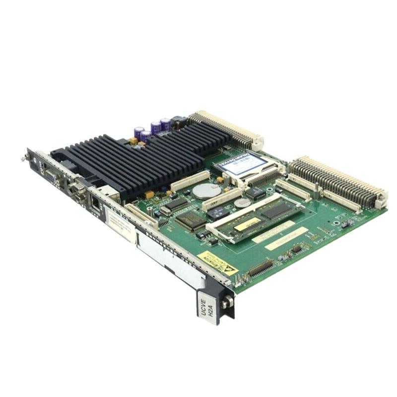
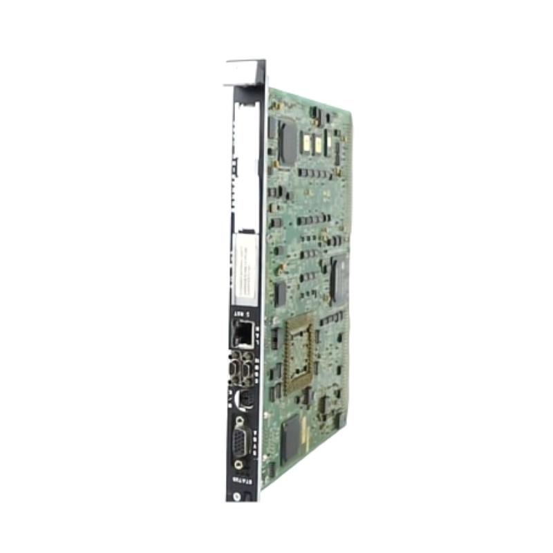
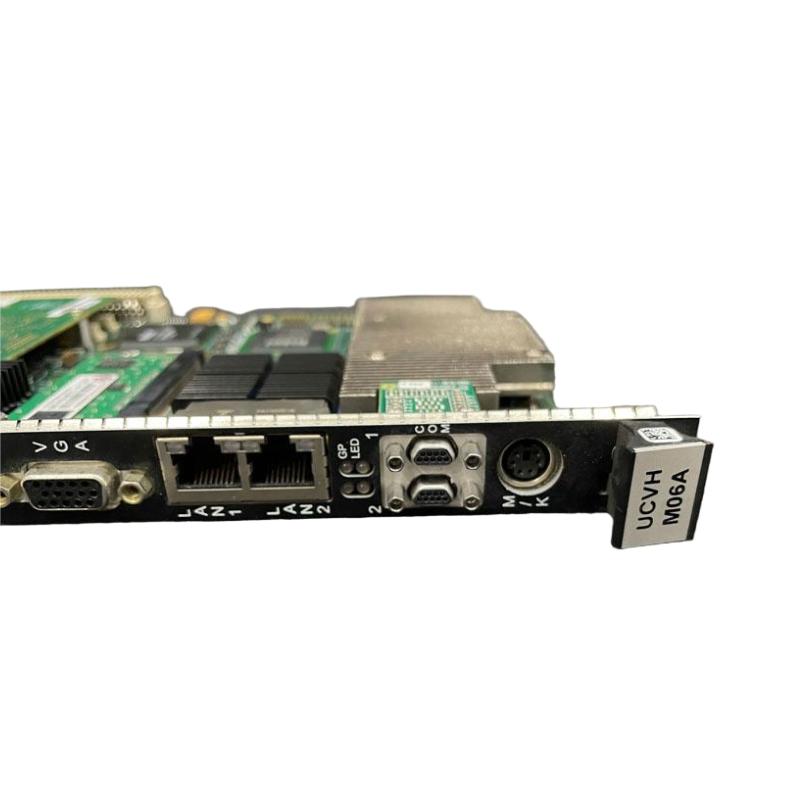
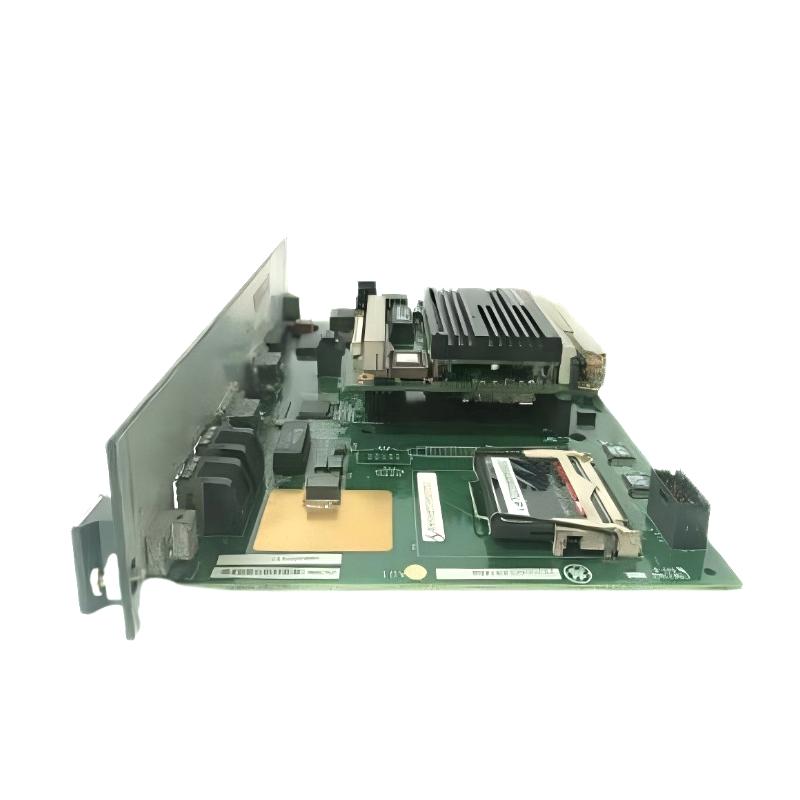
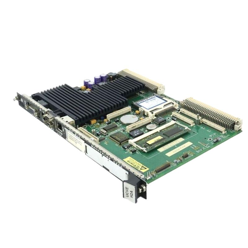
The GE IS215VPWRH2AC Mark VI Emergency Turbine Protection Board is an industrial electronic board identified with the GE Mark VI turbine control platform. Turbine control and protection systems use dedicated electronic assemblies to manage control signals, monitor equipment conditions, and coordinate responses to abnormal operating states.
Within a turbine installation, electronic boards work alongside control processors, power distribution circuits, signal interfaces, and protection-related hardware. The function of an individual board depends on its circuit design and its position within the overall system architecture. Accurate identification is therefore essential when maintaining existing turbine control equipment or sourcing a replacement assembly.
The IS215VPWRH2AC model designation provides a specific reference for spare-parts management and maintenance documentation. Although the product title identifies it as an Emergency Turbine Protection Board, the exact electrical function and system role should be distinguished from those of other Mark VI boards with similar descriptions. Model-specific identification helps reduce replacement errors and supports structured troubleshooting.
During maintenance, technicians should evaluate the board together with its power connections, connectors, associated electronics, and installed system configuration. This approach helps distinguish a board-level fault from problems involving external wiring, power distribution, or connected control components.
Technical Specifications
| Parameter | Specification |
|---|---|
| Manufacturer | GE |
| Model | IS215VPWRH2AC |
| Product Series | Mark VI |
| Product Type | Emergency Turbine Protection Board |
| Product Category | Industrial Turbine Control Electronics |
| System Application | Turbine control and protection |
| Primary Function | Electronic functions within the installed turbine control system |
| Control Platform | GE Mark VI |
| Installation Type | Industrial control system circuit board |
| System Integration | Equipment-specific turbine control architecture |
| Maintenance Method | Board inspection, fault diagnosis, and replacement |
| Dimensions | 200 × 100 × 40 mm |
| Weight | 0.75 kg |
Product Features
- GE Mark VI Emergency Turbine Protection Board
- Model IS215VPWRH2AC
- Associated with the GE Mark VI turbine control platform
- Forms part of the electronic hardware used in industrial turbine control systems
- Supports integration within a compatible turbine control and protection architecture
- Works alongside associated control electronics and designated electrical interfaces
- Supports board-level inspection and replacement during maintenance
- Requires accurate model identification when selecting replacement hardware
- Allows inspection of accessible circuitry and connectors during troubleshooting
- Supports structured maintenance and fault investigation
- Requires verification of system compatibility before installation
- Provides a specific part reference for spare-parts inventory and service records
Working Principle
The GE IS215VPWRH2AC board operates as part of the electronic assembly in which it is installed. Its precise operating sequence depends on the board’s circuit design, electrical interfaces, and assigned role within the Mark VI system.
In a turbine control installation, electronic boards exchange signals with other control-system components through designated interfaces. The wider system uses these signals to coordinate monitoring, control, and protection-related functions according to its configuration. Where a board participates in protection functions, its operation is associated with the corresponding monitoring logic and protective response arrangements.
Typical system sequence:
Signal or power interface → Electronic processing within the configured assembly → Exchange with associated control hardware → System-level control or protection response
The exact contribution of the IS215VPWRH2AC to this sequence must be determined from the installed equipment configuration. Correct operation depends on appropriate electrical connections, compatible hardware, and the intended system arrangement.
During fault diagnosis, technicians should review relevant alarms, board condition, connector integrity, power arrangements, and associated control-system diagnostics. These checks help identify whether the problem originates in the board or in another part of the installation.
Role in a Mark VI Turbine Control Architecture
Within a GE Mark VI installation, individual electronic boards operate as part of a coordinated control architecture. Depending on their assigned functions, these assemblies may support signal processing, power distribution, monitoring, or protection-related operations. The IS215VPWRH2AC should be assessed according to its verified role in the installed system rather than assumed to perform every function associated with turbine protection.
| System Component | Function | Relationship to the Board |
|---|---|---|
| Mark VI Control System | Coordinates turbine monitoring and control functions | Provides the wider system environment |
| IS215VPWRH2AC Board | Performs its assigned electronic functions | Operates within the installed control assembly |
| Power Supply | Provides operating power to electronic circuits | Supports the electrical requirements of the board and associated hardware |
| Signal Interface Circuits | Transfer signals between system components | Carry signals where supported by the configuration |
| Turbine Monitoring Sensors | Measure operating conditions | Supply information to the wider control system |
| Protection Logic | Evaluates monitored conditions against configured criteria | Determines the appropriate response to detected conditions |
| Trip or Shutdown Interface | Initiates designated protective actions | Supports system-level protection responses |
| Engineering and Diagnostic Tools | Support configuration review and fault investigation | Assist with troubleshooting and maintenance |
Industrial Applications
| Application Area | Typical Use | Relevance of the Board |
|---|---|---|
| Gas Turbine Installations | Maintenance of turbine control electronics | Provides a specific component reference for servicing |
| Steam Turbine Systems | Maintenance of compatible turbine control hardware | Supports board identification within the installed architecture |
| Power Generation Facilities | Inspection and replacement of control-system circuit boards | Helps organize spare-parts planning and maintenance records |
| Industrial Turbine Operations | Servicing of electronic assemblies used in turbine control | Supports component-level maintenance |
| Turbine Control Cabinet Maintenance | Inspection of installed electronic hardware | Allows investigation of board-related faults |
| Control System Refurbishment | Replacement of aging or faulty electronic assemblies | Requires model and compatibility verification |
| Industrial Automation Maintenance | Troubleshooting of control-system electronics | Supports structured fault diagnosis |
Installation and Maintenance
- Verify the board identification: Confirm the complete IS215VPWRH2AC model number against the installed board and equipment records.
- Review the system configuration: Identify the board’s installed position, associated hardware, and assigned function before beginning replacement work.
- Isolate the equipment: Follow the approved turbine shutdown, electrical isolation, and site safety procedures before accessing the control cabinet.
- Record the original installation: Document the board orientation, mounting arrangement, connector positions, and connected interfaces.
- Inspect the board: Examine accessible surfaces for physical damage, discoloration, cracked components, or other visible signs of abnormal conditions.
- Check the connectors: Inspect accessible connectors and terminals for contamination, corrosion, loose contacts, or signs of overheating.
- Apply ESD precautions: Use appropriate electrostatic discharge protection when handling the board and avoid unnecessary contact with exposed electronic components.
- Remove the existing board carefully: Disconnect the relevant interfaces using the proper release method and avoid applying excessive force to connectors.
- Verify the replacement hardware: Check the complete model number, hardware revision, mounting arrangement, and compatibility with the installed system.
- Install the replacement board: Position and secure the board according to the assembly requirements without forcing connectors or mounting points.
- Perform approved functional checks: Restore the system according to the site procedure and verify relevant diagnostics and operating status before returning the equipment to service.
- Document the maintenance: Record the board identification, replacement date, observed fault, diagnostic findings, and post-maintenance test results.
Related Components
| Component | Function | Relationship to the Board |
|---|---|---|
| GE Mark VI Control Hardware | Provides the wider turbine control platform | Establishes the system environment in which the board operates |
| Industrial Power Supply | Provides electrical power to control electronics | Supports the electrical requirements of the installed assembly |
| Signal Interface Board | Transfers signals between compatible system components | May interface with the board through the configured architecture |
| Turbine Monitoring Sensors | Measure operating parameters | Supply signals used by monitoring and control functions |
| Turbine Protection Electronics | Supports protection-related signal processing and control | May operate alongside the board within the wider system |
| Trip Interface Circuit | Carries commands to designated protective mechanisms | Supports system-level protective actions where configured |
| Control Cabinet Assembly | Houses and connects electronic boards | Provides the physical installation environment |
Recommended Related Models
| Model or Product Category | Product Type | Relationship |
|---|---|---|
| GE IS215VPWRH2AC Mark VI | Emergency Turbine Protection Board | Specified board for identification and replacement |
| GE IS215VPROH2BC Mark VI | Emergency Turbine Protection Board | Related model requiring separate compatibility verification |
| GE IS215VPROH2BD Mark VI | Emergency Turbine Protection Board | Related model requiring separate compatibility verification |
| GE Mark VI Control Boards | Industrial Control Circuit Boards | Related category for turbine control electronics |
| GE Mark VI Interface Boards | Signal Interface Components | Related category for compatible control-system interfaces |
| GE Mark VI Power Supply Modules | Power Supply Components | Related category supporting the control electronics |
Key Advantages
- Specific Part Identification: The complete model number supports accurate spare-parts selection and maintenance records.
- Mark VI Platform Association: Identifies the board within the GE Mark VI turbine control equipment family.
- Board-Level Maintenance: Supports inspection and replacement of the individual electronic assembly when appropriate.
- Structured Fault Diagnosis: Encourages investigation of the board alongside its power, signal, and interface connections.
- Maintenance Traceability: Supports documentation of replacement work and diagnostic findings.
- Equipment Lifecycle Support: Provides a specific component reference for maintaining existing turbine control installations.
Technical FAQs
What is the GE IS215VPWRH2AC used for?
The IS215VPWRH2AC is identified by the supplied product title as a GE Mark VI Emergency Turbine Protection Board. Its exact electronic responsibilities depend on the board’s hardware design and installed system configuration.
Is the IS215VPWRH2AC interchangeable with other Mark VI boards?
Interchangeability should not be assumed based on the product family or similar descriptions. The complete model number, revision, electrical interfaces, and system compatibility must match the intended installation.
What should technicians check when troubleshooting this board?
Inspect the board’s physical condition, connectors, power arrangements, associated wiring, and relevant system diagnostics. These checks help distinguish a board-level fault from a problem elsewhere in the control assembly.
Why is accurate model identification important when replacing turbine control boards?
Turbine control systems use coordinated electronic assemblies with specific electrical and system interfaces. Correct identification helps reduce installation errors and supports the intended operation of the existing control architecture.