

ProductPRODUCT
Featured products
Contact Us
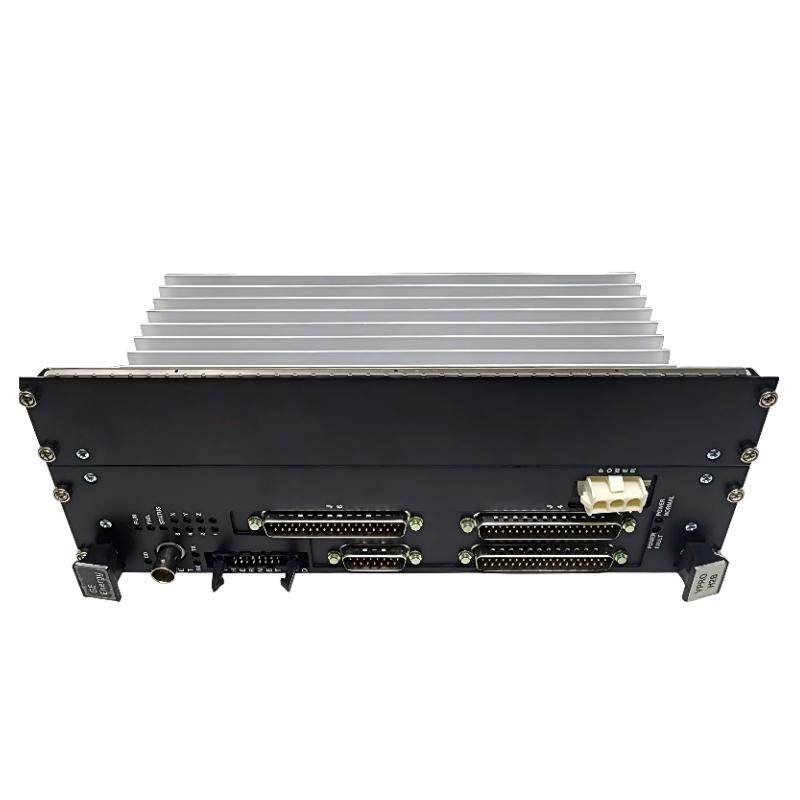
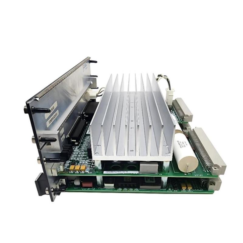
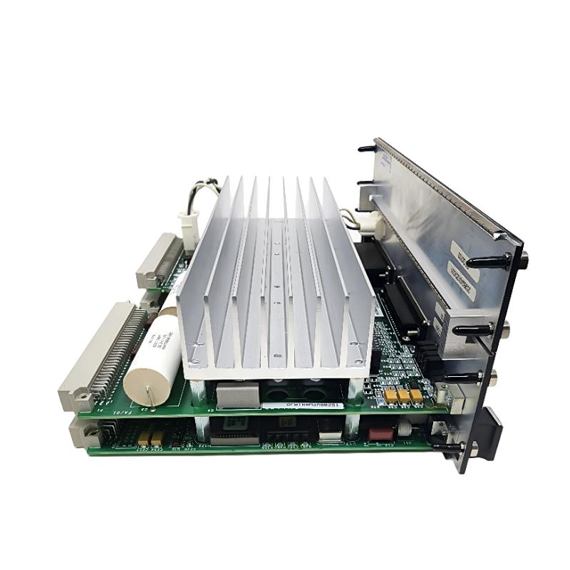
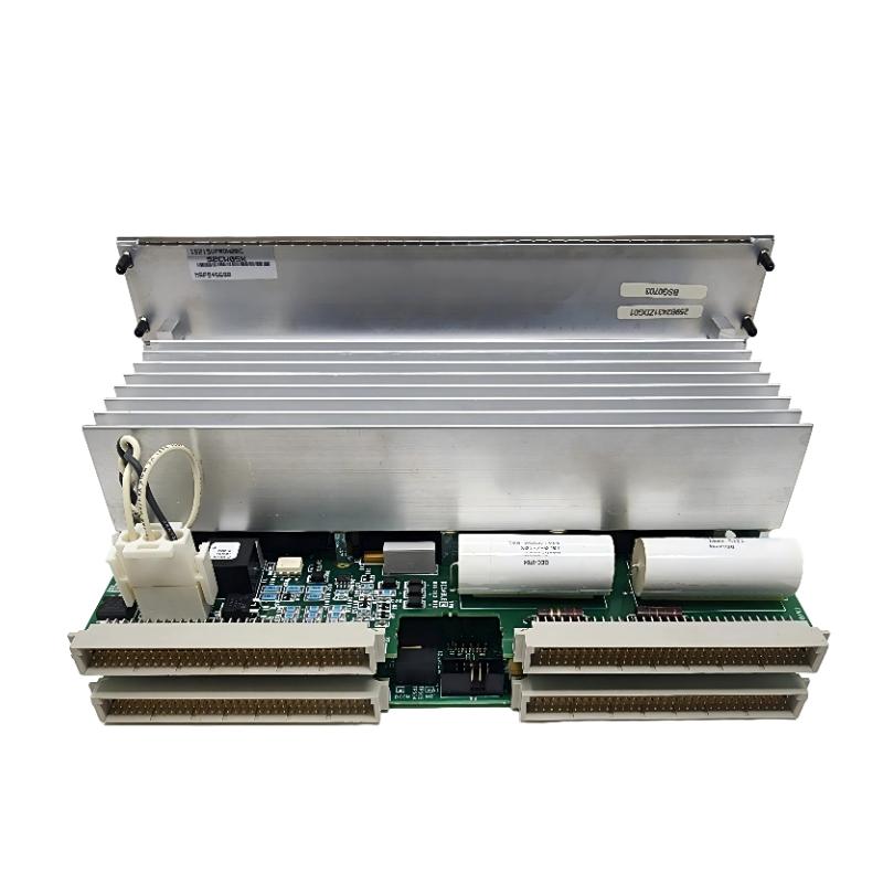
- GE
- IS215VPROH2B IS215VPWRH2AC
- Emergency Turbine Protection Board Assembly
- USA
- 200 × 150 × 30 mm
- 0.5 kg
- Xiamen, China
- New & In Stock
- T/T, PayPal, Western Union
- 1 Year
- 1-3 Working Days
- DHL, UPS, TNT, FedEx and EMS.
- 24-Hour Service
- COO
- 4
Our advantage

Global Logistics
We have a 10-year logistics and express cooperation agreement, so our products can be shipped to any place in the world.

Brand new and original
Our products are imported in bulk from the place of origin. Because of the cooperative relationship, our products are all original and 100% new.

24-hour service
We provide 7*24 hours service to our customers. We will be there whenever you need us.

Price advantage
All our products are priced very favorably because we have our own warehouse and supply.
| Company Information | |||
| [email protected] | |||
| Mobile | +8615980777398 | ||
| +8615980777398 | |||
| 15980777398 |
Product Overview
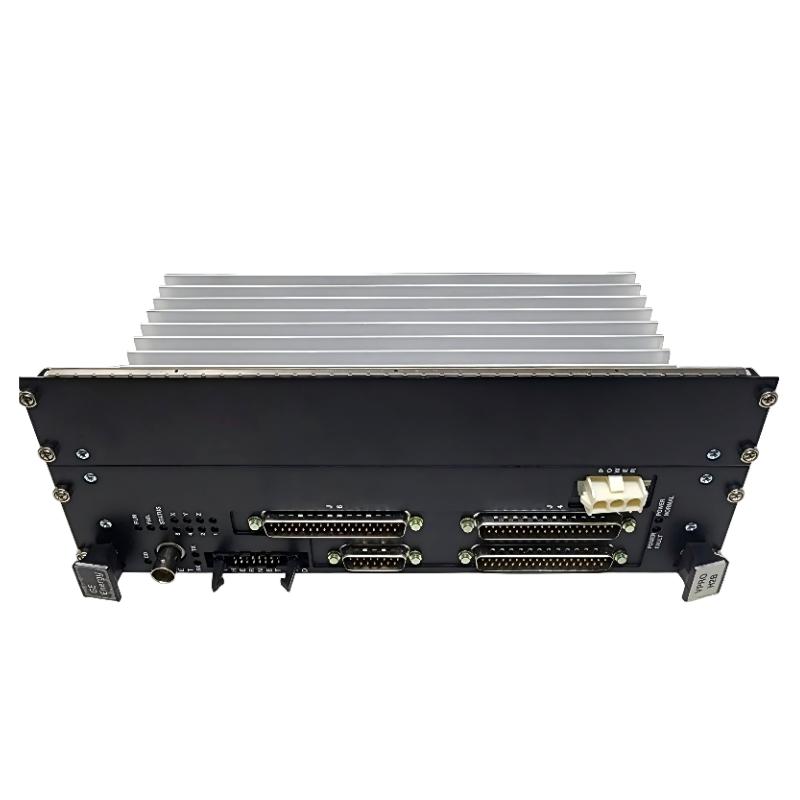
The GE IS215VPROH2B IS215VPWRH2AC Mark VI Emergency Turbine Protection Board Assembly is associated with the emergency protection hardware used in GE Speedtronic Mark VI turbine control systems. Its principal application is turbine protection, particularly overspeed detection and emergency trip functions that must operate independently of normal turbine regulation.
In a gas turbine installation, normal control hardware adjusts fuel, speed, and operating conditions during startup, synchronization, loading, and steady operation. The protection system serves a different purpose. It monitors assigned protection signals and initiates a trip when a configured dangerous condition occurs. The VPRO protection board processes these inputs and controls the trip-relay circuits through the associated TREG terminal board.
The Mark VI protection arrangement commonly uses three VPRO channels in a separate protection module. Each channel has its own onboard power supply, and the channels participate in the configured protection logic. This separation allows the system to distinguish normal control activity from emergency protection actions.
The two identifiers in this product title should be retained when recording or sourcing the assembly. IS215VPROH2B identifies the VPRO protection-board variant, while IS215VPWRH2AC is an additional assembly identifier associated with the listed product. Because board and power-supply references can represent different hardware functions, replacement work should confirm the installed assembly and its component references rather than assuming both numbers identify the same individual circuit board.
Technical Specifications
| Parameter | Specification |
|---|---|
| Manufacturer | General Electric (GE) |
| Product Model | IS215VPROH2B |
| Additional Part Number | IS215VPWRH2AC |
| Product Family | Speedtronic Mark VI |
| Product Type | Emergency Turbine Protection Board Assembly |
| Primary Function | Emergency turbine protection and trip control |
| Protection Architecture | VPRO turbine protection system |
| Protection Functions | Emergency overspeed protection and emergency-stop functions |
| Associated Terminal Boards | TPRO and TREG |
| Trip Circuit Interface | TREG relay circuits; associated TRPG hardware in the trip-solenoid arrangement |
| Communication Interface | Ethernet connection for IONet communications |
| Power Architecture | Onboard power conversion; 125 V DC trip-system supply is used in the documented Mark VI arrangement |
| Dimensions | 200 × 150 × 30 mm |
| Weight | 0.5 kg |
Product Features
- Emergency overspeed protection: Processes configured speed signals to detect conditions that require a turbine trip.
- Independent protection function: Operates within a protection subsystem separate from normal turbine control.
- Trip-relay control: Controls the 12 relays on the associated TREG terminal board, including relays used in the trip-solenoid voting circuits.
- Redundant protection architecture: Supports Mark VI protection arrangements using multiple VPRO channels.
- Dedicated protection inputs: Works with the relevant terminal-board connections for speed pickups and other configured protection signals.
- IONet communications: Includes an Ethernet connection used for communication with relevant control-system components.
- Board-level diagnostics: Supports monitoring of protection inputs, relay operation, and relevant voltage conditions.
- Variant-specific hardware: The H2B version has lower power capability than the H1A/H1B variants and does not support driving a second TREG board through connector J4.
Working Principle
The VPRO protection board receives signals from the protection system’s configured sensors and terminal interfaces. Speed pickups provide the signals used for overspeed protection, while other connected inputs may be used for emergency-stop, synchronization-check, thermocouple, or analog protection functions according to the application.
The board processes the incoming signals using its configured protection logic. If a valid trip condition is detected, it operates the relevant relay outputs on the TREG terminal board. The relay circuits then control the turbine trip solenoids, initiating the shutdown mechanism.
A simplified protection path is:
Turbine Speed Pickups and Protection Inputs → VPRO Board → TREG Trip Relays → Trip Solenoids → Turbine Trip Mechanism
In the documented Mark VI arrangement, the TREG terminal board supplies the positive side of the 125 V DC trip-solenoid circuit, while the associated TRPG board supplies the negative side. The relay voting arrangement determines how the protection channels and trip circuits respond to the configured conditions.
The VPRO board also monitors aspects of its own operating condition. Diagnostic coverage includes protection input health, reference voltages, relay drivers and feedback, solenoid voltage, and related power conditions. These diagnostics help maintenance engineers distinguish a genuine protection demand from a hardware fault or a problem in the external trip circuit.
The H2B variant’s power and terminal-board limitations matter during system configuration. Where the application requires a second TREG board driven through J4, the H2B variant is not the appropriate choice; the compatible H1A/H1B arrangement must be considered instead.
Role in a GE Mark VI Turbine Protection Architecture
The IS215VPROH2B sits in the dedicated turbine protection subsystem. It processes protection signals and controls the relay interface that initiates an emergency trip, while the normal Mark VI control hardware continues to manage routine turbine operation.
The protection module is separate from the main control system. In a typical triple-redundant arrangement, three VPRO boards process their assigned inputs, and the protection architecture uses relay voting to control the trip solenoids. The VPRO board controls 12 relays on TREG; nine of these are arranged in three groups of three for voting functions associated with the three trip-solenoid circuits.
| System Component | Function |
|---|---|
| IS215VPROH2B VPRO Board | Processes assigned turbine protection inputs and controls the TREG relay interface. |
| IS215VPWRH2AC | Additional part number associated with the listed assembly; confirm its precise role against the installed hardware identification. |
| TPRO Terminal Board | Interfaces with the VPRO protection channels and relevant protection inputs, including speed signals. |
| TREG Terminal Board | Houses the relay circuits used to control the turbine trip-solenoid arrangement. |
| TRPG Terminal Board | Provides the corresponding negative-side connection in the documented trip-solenoid circuit. |
| Turbine Speed Pickups | Provide speed measurements used by the overspeed protection logic. |
| Trip Solenoids | Actuate the turbine trip mechanism when the trip circuit operates. |
| Mark VI Control Modules | Perform normal turbine control and exchange relevant system status information. |
The H2B designation is significant when checking the protection architecture. Unlike the H1A/H1B variants, the H2B does not support a second TREG board through J4. A replacement must therefore match the actual terminal-board arrangement, power requirements, and protection configuration—not merely the general Mark VI family.
Industrial Applications
| Application | Protection Use |
|---|---|
| Gas Turbine Power Generation | Detects configured overspeed and emergency conditions and initiates the protection response. |
| Steam Turbine Control | Used in compatible Mark VI turbine protection installations. |
| Combined-Cycle Power Plants | Forms part of the emergency protection subsystem for turbine equipment. |
| Overspeed Protection | Processes speed-pickup signals against configured protection thresholds. |
| Emergency Shutdown Systems | Controls relay circuits associated with the turbine trip mechanism. |
| Turbine Synchronization | Supports backup synchronization-check functions where configured. |
| Turbine Temperature Protection | Can process selected thermocouple inputs used by configured protection functions. |
| Turbine Control System Maintenance | Serviced or replaced when the corresponding Mark VI protection hardware requires repair or refurbishment. |
Installation and Maintenance
- Confirm both identifiers. Check IS215VPROH2B and IS215VPWRH2AC against the installed assembly labels, hardware records, and replacement requirements.
- Verify the protection configuration. Identify the number of VPRO channels, the associated TPRO and TREG terminal boards, and whether a second TREG board is installed.
- Check H2B compatibility. Confirm that the existing design does not require a second TREG board driven through J4. If it does, the H2B variant is not a direct match for that arrangement.
- Follow the approved isolation procedure. Apply the site’s turbine protection maintenance and lockout requirements before removing the board assembly. Do not assume that redundant channels make live removal permissible.
- Inspect the VME rack and connectors. Check board guides, edge connectors, retaining screws, front-panel connectors, and power connections for damage or contamination.
- Label the connected cables. Record the cable positions at the board’s relevant front-panel connectors before removal to prevent incorrect reconnection of protection and trip-related wiring.
- Install the correct hardware. Seat the replacement assembly using the specified procedure and secure its retaining hardware without forcing the connectors.
- Restore power under the approved procedure. Confirm the required supply connections and check the board’s RUN, FAIL, and STAT indications, where applicable.
- Verify protection input status. Check the configured speed signals and other assigned protection inputs using the approved diagnostic tools and test procedures.
- Inspect the trip-relay path. Check the TREG relay status, feedback signals, and associated trip-circuit voltage indications when investigating a trip-output problem.
- Perform authorized protection tests. Verify the required protection functions and trip path according to the plant’s approved test procedure. Avoid unplanned trip commands or tests that could affect operating equipment.
- Confirm restoration of protection coverage. Check that the channel and associated protection hardware return to the intended operating state and that no unresolved diagnostics remain.
- Document the replacement. Record both part numbers, hardware revisions, terminal-board configuration, diagnostic results, and the outcome of the protection tests.
Since the VPRO assembly participates in emergency turbine protection, maintenance must preserve the required protection coverage throughout the work. Channel isolation, testing, and return to service should be controlled by the plant’s established turbine protection procedures.
Related Components
| Component | Function |
|---|---|
| GE IS200TPRO Terminal Board | Interfaces the VPRO protection channels with relevant protection inputs. |
| GE TREG Terminal Board | Provides relay circuits for the turbine trip-solenoid interface. |
| GE TRPG Terminal Board | Provides the negative-side connection for the trip-solenoid circuit in the documented arrangement. |
| Turbine Magnetic Speed Pickups | Supply speed signals used by the overspeed protection logic. |
| Turbine Trip Solenoids | Actuate the emergency trip mechanism. |
| Mark VI VME Rack | Provides mounting and electrical interconnections for compatible protection boards. |
| Protection-System Power Connections | Supply the required operating and trip-circuit power to the installed protection arrangement. |
Recommended Related Models
| Model / Component | Product Type | Selection Consideration |
|---|---|---|
| GE IS215VPROH1B | VPRO Turbine Protection Board | Consider where the configuration requires support for a second TREG board through J4; confirm the complete system requirements. |
| GE IS215VPROH1A | VPRO Turbine Protection Board | Compare the hardware revision and terminal-board arrangement before considering replacement. |
| GE IS200SPROH1ACC | Protection Processor Board | Belongs to a different protection hardware arrangement and is not a direct substitute for the VPRO board. |
| GE IS200TPRO | Protection Input Terminal Board | Relevant to the VPRO speed and other protection-input connections. |
| GE TREG | Turbine Emergency Trip Terminal Board | Relevant when checking trip-relay compatibility and solenoid circuit wiring. |
| GE TRPG | Trip Relay Power Terminal Board | Relevant to the trip-solenoid power path and associated connections. |
Key Advantages
- Provides dedicated emergency turbine protection within the Mark VI platform.
- Supports overspeed detection and emergency trip control.
- Controls the TREG relay interface used by the trip-solenoid circuits.
- Works within a redundant protection architecture.
- Offers diagnostic information for input, relay, and voltage-related faults.
- Has a defined H2B configuration that can be checked against the installed terminal-board arrangement.
Technical FAQs
1. What is the main function of the IS215VPROH2B?
The IS215VPROH2B is a VPRO emergency turbine protection board for GE Mark VI systems. It processes configured protection signals, including speed inputs used for overspeed detection, and controls the associated TREG trip-relay circuits.
2. What is the difference between the VPROH2B and VPROH1B variants?
The key configuration difference is support for a second TREG board. The H1A/H1B variants can drive a second TREG board through connector J4, whereas the H2B is a lower-power version that omits this capability. The existing terminal-board arrangement must be checked before selecting a replacement.
3. How does the VPRO board initiate a turbine trip?
When its configured protection logic detects a trip condition, the board operates the appropriate relays on TREG. These relays participate in the trip-solenoid voting circuits, which actuate the turbine’s emergency trip mechanism. The actual trip response depends on the installed protection design and configuration.
4. What should be checked if the VPRO board reports a fault or fails a protection test?
Check the board’s diagnostic indications, rack seating, power connections, speed and other protection inputs, TPRO/TREG wiring, relay feedback, and trip-circuit voltage. Use the approved diagnostic and test procedures to distinguish a board fault from a sensor, terminal-board, or external trip-circuit problem.