
NewsNEWCENTER
Featured products
Contact Us
Schneider 140ACI04000 Analog Input Module Troubleshooting Guide
2026-09-28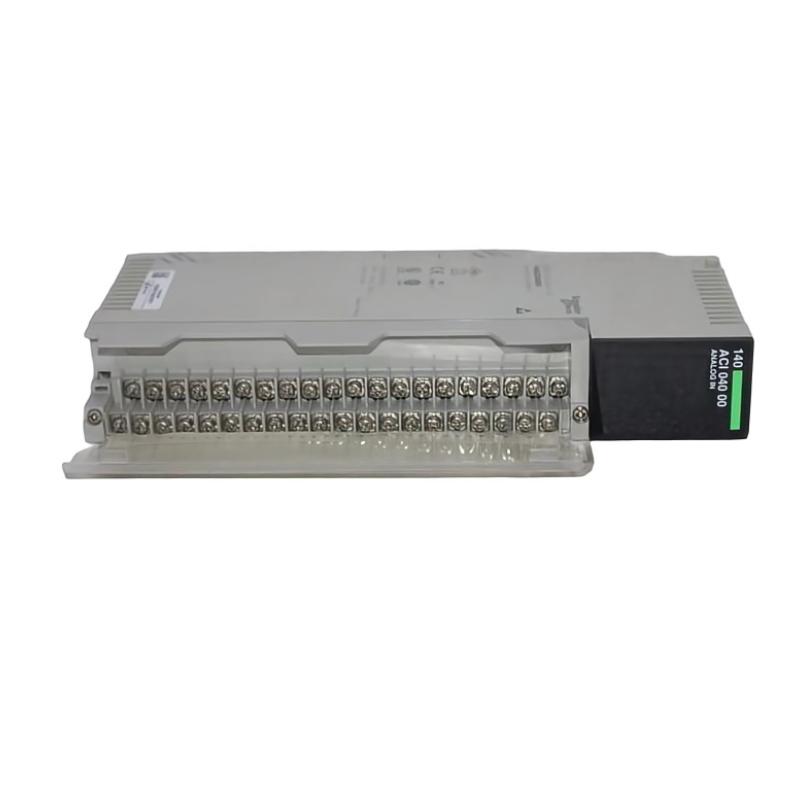
Troubleshooting the Schneider 140ACI04000 analog input module requires checking the entire analog measurement path rather than assuming that an incorrect PLC value indicates module failure. Field instruments, signal wiring, channel configuration, grounding, electrical interference, rack communication, and scaling can all affect the value displayed by the control system.
Schneider 140ACI04000 Fault Diagnosis Overview
An analog input problem may appear as a zero reading, incorrect process value, unstable signal, missing channel, or module diagnostic condition. The most effective approach is to determine where the actual signal begins to differ from the expected value.
Field Instrument
      |
      v
Signal Wiring
      |
      v
Terminal / Channel
      |
      v
140ACI04000
      |
      v
Quantum Backplane
      |
      v
Controller
      |
      v
Engineering Value
This signal-path approach makes it easier to distinguish a field-device problem from a wiring, configuration, or module problem.
Schneider 140ACI04000 Common Fault Symptoms
- Analog input remains at zero.
- Input value is consistently too high or too low.
- Input value fluctuates unexpectedly.
- One channel behaves differently from other channels.
- Several input channels become abnormal at the same time.
- The controller reports an I/O or module diagnostic condition.
- Input value does not respond to process changes.
- PLC value does not agree with the field instrument.
- Signal becomes unstable when nearby electrical equipment operates.
Common Causes of Schneider 140ACI04000 Faults
| Fault Symptom | Possible Cause | Recommended Check |
|---|---|---|
| Zero reading | Missing field signal or wiring problem | Trace the complete signal circuit |
| Incorrect but stable value | Configuration or scaling problem | Verify channel setup and engineering units |
| Unstable reading | Interference or poor connection | Inspect routing, shielding, grounding, and terminals |
| One channel abnormal | Field device or channel-specific problem | Check the individual signal path |
| Multiple channels abnormal | Common rack, configuration, or power condition | Investigate shared system conditions |
| Module unavailable | Rack, backplane, or configuration problem | Check module seating and controller diagnostics |
Schneider 140ACI04000 Troubleshooting Diagnostic Logic
Analog Input Fault
       |
       v
Check Controller Diagnostics
       |
       v
Is 140ACI04000 Recognized?
       |
    +--+--+
    |     |
   No    Yes
    |     |
Check    Check
Rack     Channel
and      Configuration
Backplane     |
              v
        Check Field Signal
              |
              v
        Check Wiring
              |
              v
        Check Scaling
              |
              v
        Check Interference
              |
              v
        Evaluate Module
This diagnostic sequence helps prevent unnecessary module replacement by checking the surrounding system first.
Schneider 140ACI04000 Testing and Fault Analysis
Check the Module Status
Begin by confirming whether the controller recognizes the 140ACI04000 correctly. If the complete module is unavailable, inspect the rack position, backplane connection, configuration, and system diagnostics before focusing on an individual analog channel.
Check the Field Instrument
Confirm that the connected transmitter or sensor is producing the expected signal. If the field instrument is defective or incorrectly configured, the input module cannot produce the correct process value.
Check the Signal Wiring
Inspect signal conductors, terminals, connectors, cable condition, channel assignments, and grounding. Pay particular attention to modifications made shortly before the fault appeared.
Field Instrument
      |
      v
Cable
      |
      v
Terminal
      |
      v
140ACI04000 Channel
      |
      v
Controller
      |
      v
Displayed Value
Test the signal path step by step. The point at which the expected value disappears or changes unexpectedly provides an important clue to the fault location.
Check Channel Configuration and Scaling
A stable but incorrect value frequently points toward configuration or scaling rather than an intermittent hardware failure. Confirm that the channel configuration corresponds to the actual connected field device and that the PLC application converts the input data into the correct engineering units.
Check for Electrical Interference
When an analog value fluctuates, inspect cable routing, shielding, grounding, nearby variable-speed drives, contactors, motors, and switching equipment. Compare the PLC reading with the actual field signal if appropriate test equipment is available.
Schneider 140ACI04000 Detailed Fault Isolation
When appropriate, comparison with a known-good compatible channel can help narrow the problem. The comparison is useful only when both channels have compatible configurations and similar field conditions.
Suspected Channel:
Field Signal -> Normal
PLC Value -> Abnormal

Reference Channel:
Field Signal -> Normal
PLC Value -> Normal

Next Diagnostic Steps:
Check suspected channel wiring
Check configuration
Check scaling
Check terminal condition
Evaluate input path
If several channels fail simultaneously, investigate common causes before replacing individual components. Shared rack conditions, configuration changes, grounding problems, power disturbances, or environmental interference can affect multiple channels at once.
Schneider 140ACI04000 Repair and Replacement Procedure
When evidence indicates a hardware problem, document the existing installation before removing the module.
- Place the controlled process in a safe maintenance state.
- Record the module position and channel assignments.
- Record current diagnostic information.
- Document field wiring before disconnection.
- Follow the approved procedure for module removal.
- Inspect the rack and backplane connector.
- Install the correct replacement module.
- Reconnect field wiring carefully.
- Verify channel configuration and scaling.
- Restore the required controller configuration.
- Test each affected analog channel.
- Perform a controlled process functional test.
Do not replace the 140ACI04000 simply because a single analog value is incorrect. The field device, wiring, configuration, scaling, grounding, and signal environment should be eliminated as possible causes first.
Schneider 140ACI04000 Field Troubleshooting Case
Representative example: One analog process value begins fluctuating while the local transmitter appears stable. The module remains visible to the controller, so the technician investigates signal integrity.
Observed:
PLC analog value fluctuates

Module:
Recognized by controller

Field Instrument:
Stable

Inspection:
Analog cable routed close to switching equipment

Diagnostic Direction:
Investigate electromagnetic interference,
shielding, grounding, and cable routing

Final Validation:
PLC value becomes stable after corrective action
This is a representative troubleshooting scenario rather than a verified manufacturer field case. It illustrates why analog instability should be investigated across the complete signal path before assuming an input-module hardware failure.
Schneider 140ACI04000 Troubleshooting FAQ
Why does the Schneider 140ACI04000 show zero on an input?
Possible causes include a missing field signal, broken conductor, incorrect channel assignment, configuration error, field-instrument problem, or an input-path fault. Trace the signal from the field device to the controller.
Why is the analog value stable but incorrect?
Check channel configuration, scaling, field-device output, wiring, and engineering-unit conversion. A stable incorrect value is not necessarily evidence of a failed module.
Why does only one channel fail?
A single-channel problem can be caused by the connected instrument, local wiring, terminal connection, channel configuration, or a localized input fault.
Why are several channels abnormal simultaneously?
Multiple-channel problems should prompt an investigation of common conditions such as rack configuration, backplane connections, power, grounding, or electrical interference.
When should the 140ACI04000 be replaced?
Replacement should be considered after field-device, wiring, configuration, scaling, grounding, and environmental causes have been investigated and the available evidence indicates a hardware problem.
Schneider 140ACI04000 Technical Summary
The Schneider 140ACI04000 analog input module is a critical interface between field instrumentation and the industrial control system. Effective fault diagnosis requires tracing the complete signal path from the field instrument through wiring and the input channel to the controller and engineering value. By checking configuration, scaling, signal integrity, grounding, and rack conditions before replacing hardware, maintenance personnel can isolate analog input faults more efficiently and restore reliable process measurement.