

ProductPRODUCT
Featured products
Contact Us
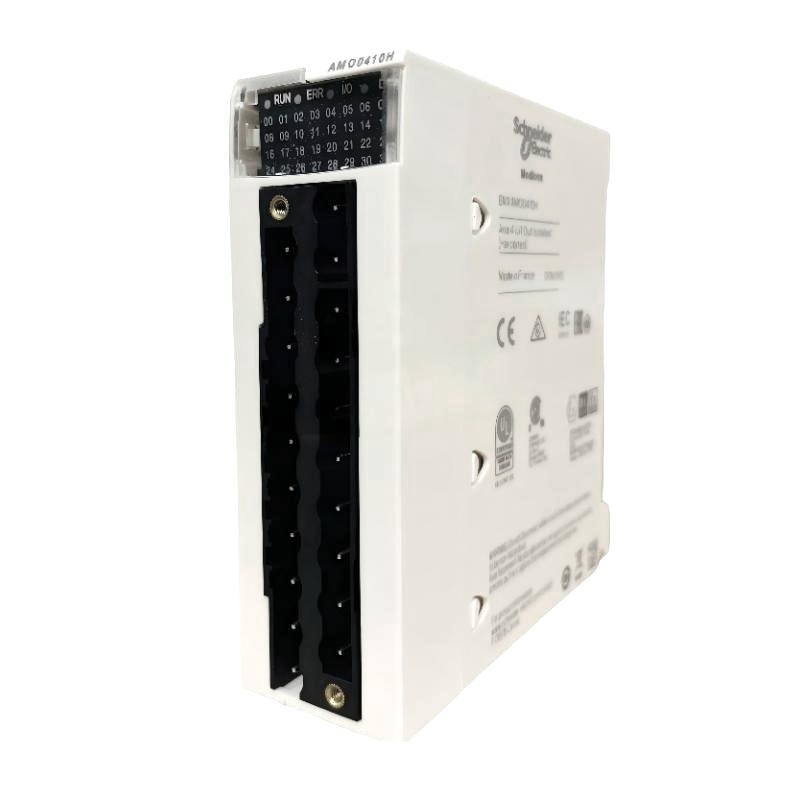
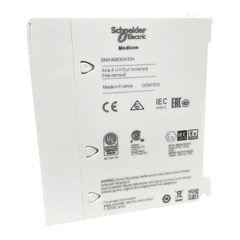
- Schneider
- BMXAMO0410H
- Analog Output Module
- France
- 118 x 116 x 55 mm
- 0.15 kg
- Xiamen, China
- New & In Stock
- T/T, PayPal, Western Union
- 1 Year
- 1-3 Working Days
- DHL, UPS, TNT, FedEx and EMS.
- 24-Hour Service
- COO
- 6
Our advantage

Global Logistics
We have a 10-year logistics and express cooperation agreement, so our products can be shipped to any place in the world.

Brand new and original
Our products are imported in bulk from the place of origin. Because of the cooperative relationship, our products are all original and 100% new.

24-hour service
We provide 7*24 hours service to our customers. We will be there whenever you need us.

Price advantage
All our products are priced very favorably because we have our own warehouse and supply.
| Company Information | |||
| [email protected] | |||
| Mobile | +8615980777398 | ||
| +8615980777398 | |||
| 15980777398 |
Product Overview
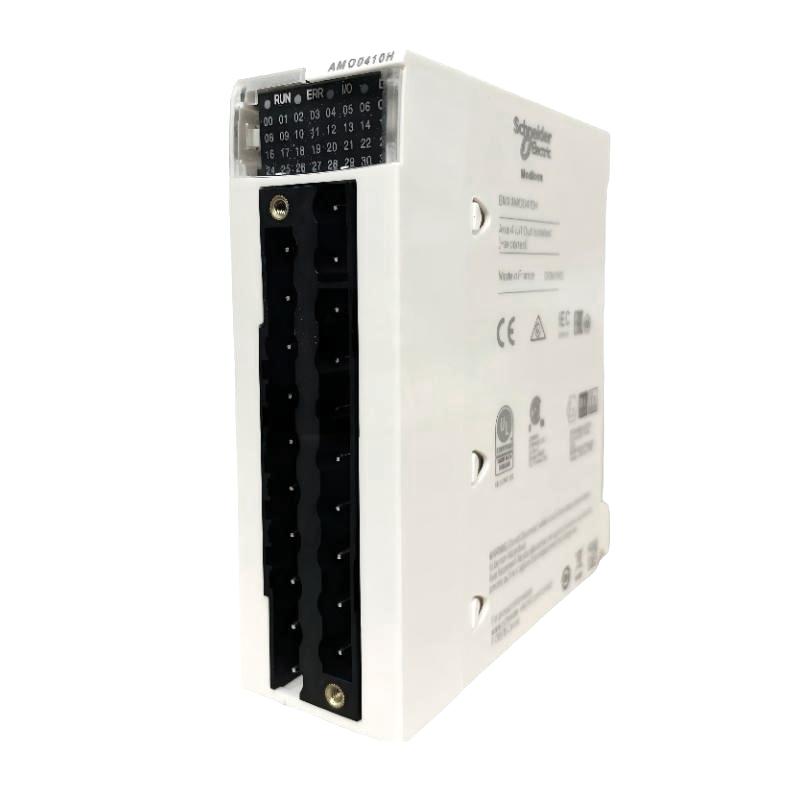
The Schneider BMXAMO0410H Analog Output Module is an industrial automation I/O component designed to provide analog control signals from a PLC system to connected field devices. Unlike digital outputs, which generally provide discrete ON/OFF commands, an analog output can generate a continuously variable control signal that represents a desired process value or equipment operating level.
Analog output modules are widely used in industrial automation because many field devices require continuously adjustable commands. Depending on the application, an analog output can be used to control a valve position, motor speed reference, pressure setpoint, flow-control device, actuator, or other process equipment.
The BMXAMO0410H provides the interface between the PLC control logic and analog field equipment. The controller calculates the required output value based on process conditions, operator commands, programmed sequences, or closed-loop control algorithms. The analog output module then provides the corresponding electrical output to the connected field device.
The supplied physical specifications for the Schneider BMXAMO0410H are 118 × 116 × 55 mm, with a weight of 0.15 kg. These dimensions are useful for PLC rack planning, cabinet layout, replacement preparation, and spare-parts management.
Exact output signal types, channel configuration, resolution, accuracy, load characteristics, isolation, wiring assignments, and diagnostic functions should be confirmed against the applicable Schneider Electric documentation for the specific BMXAMO0410H installation.
Technical Specifications
| Parameter | Specification |
|---|---|
| Manufacturer | Schneider Electric |
| Model | BMXAMO0410H |
| Product Type | Analog Output Module |
| Primary Function | Analog Signal Generation |
| System Role | PLC / Process Output |
| Application | Industrial Automation and Process Control |
| Dimensions | 118 × 116 × 55 mm |
| Weight | 0.15 kg |
| Installation | Modular PLC / I/O System |
| Typical Applications | Process Control, Valve Control, Drive References, Machine Automation |
The dimensions and weight above are based on the product information supplied for this article. Detailed electrical and performance characteristics should be confirmed against the applicable Schneider Electric technical documentation.
What Is the Schneider BMXAMO0410H?
The Schneider BMXAMO0410H is identified as an Analog Output Module used to convert controller commands into analog signals for field equipment.
A PLC does not directly control every industrial actuator through internal processor logic. Instead, I/O modules provide the interface between the controller and physical equipment.
For analog control, the architecture can be represented as:
PLC Control Logic → BMXAMO0410H → Analog Output Signal → Field Device
The field device may then adjust its operating condition according to the received signal.
For example, a PLC can calculate a required valve position and send the corresponding analog command through the analog output module. The valve control system receives the signal and adjusts the valve accordingly.
Analog Output Working Principle
The operation of an analog output system can be divided into several stages.
Control Setpoint
The PLC application determines the required output value.
This value may originate from:
- Operator input
- Process measurement
- Automatic control logic
- PID control
- Production sequence
- Equipment status
- Supervisory commands
Digital Control Value
The PLC internally represents the required output as a digital value.
The control program determines the relationship between the digital value and the desired engineering value.
Analog Conversion
The analog output module converts the configured digital command into the appropriate electrical output signal.
The connected field device interprets the signal as a control command.
Field Device Response
The receiving device changes its physical operating condition according to the command.
Examples include:
- Valve opening
- Actuator position
- Motor speed reference
- Pressure setpoint
- Flow-control command
This creates the basic relationship:
PLC → Analog Output → Field Device → Process Response
Analog Output Scaling
Correct scaling is one of the most important considerations when commissioning an analog output system.
The PLC program typically establishes a relationship between a digital control value and a physical engineering range.
For example:
PLC Value → Output Signal → Engineering Value
The engineering value might represent:
- Valve position percentage
- Motor speed
- Pressure
- Flow
- Temperature setpoint
- Equipment operating level
Incorrect scaling can cause a field device to operate at an unintended level even though the analog output hardware is functioning correctly.
For this reason, scaling should be tested during commissioning before the equipment is placed into automatic production operation.
Role in Industrial Control Systems
The BMXAMO0410H can serve as the output interface between PLC control logic and analog field equipment.
A typical process-control architecture can be represented as:
Sensors → Analog Input → PLC → BMXAMO0410H → Actuator → Process
This creates a closed control loop.
For example:
- A sensor measures process pressure.
- The analog input system transfers the measurement to the PLC.
- The PLC calculates the required response.
- The BMXAMO0410H generates an analog control command.
- A valve or other actuator responds.
- The process changes.
- The sensor provides updated feedback.
This type of architecture is fundamental to automated process control.
Industrial Applications
Valve Control
Analog outputs are frequently used to control modulating valves.
The PLC can generate a variable command corresponding to the required valve position.
Applications include:
- Water flow regulation
- Chemical dosing
- Steam control
- Pressure regulation
- Process temperature control
Variable-Speed Drive References
In some control architectures, an analog output can provide a speed or process reference to a compatible motor drive.
The PLC can adjust the reference according to:
- Process demand
- Operator settings
- Feedback values
- Production requirements
The exact signal interface must match the drive requirements.
Process Control
Analog outputs are commonly used in closed-loop process-control systems.
Applications can include:
- Pressure control
- Flow control
- Level control
- Temperature control
- Chemical concentration control
Industrial Machinery
Automated machinery may use analog commands to control actuators or equipment requiring continuously variable operation.
Utility Systems
Industrial utility equipment can use analog control signals for pumps, fans, valves, and other process devices.
PLC Integration
The BMXAMO0410H operates as part of a modular PLC architecture.
A typical control structure includes:
PLC CPU → BMXAMO0410H → Analog Field Device
The PLC program determines the output command while the module provides the physical interface.
The control program may contain:
- Manual control
- Automatic sequences
- PID loops
- Interlocks
- Alarm handling
- Output limiting
- Equipment control
The exact PLC rack arrangement and hardware compatibility should be confirmed for the intended Schneider Electric platform.
HMI Integration
An HMI can provide operators with control over analog output values.
For example, an HMI may allow an operator to enter:
- Valve position
- Speed reference
- Pressure setpoint
- Flow setpoint
- Temperature setpoint
The operator command is passed to the PLC, where application logic determines the appropriate output.
The communication path can be represented as:
Operator → HMI → PLC → BMXAMO0410H → Field Device
Appropriate software limits and interlocks should be implemented to prevent unsafe or unintended output commands.
SCADA Integration
In larger industrial facilities, analog output information may be integrated with SCADA systems.
Supervisory systems can allow operators and engineers to monitor:
- Output values
- Process responses
- Equipment status
- Control setpoints
- Alarms
- Historical trends
Depending on the overall architecture, supervisory commands can also be passed to the PLC and ultimately converted into analog field commands.
Installation Guidelines
Proper installation is essential for reliable analog output operation.
Verify Module Identification
Confirm the complete model designation:
Schneider BMXAMO0410H
Check the product label before installation.
Confirm Physical Dimensions
The supplied dimensions are:
118 × 116 × 55 mm
The cabinet or PLC rack should provide adequate space for the module and connected wiring.
Inspect Wiring
Before commissioning, verify:
- Output wiring
- Terminal connections
- Cable condition
- Device connections
- Shielding and grounding arrangements
Separate Analog Wiring From High-Power Conductors
Analog output signals can be affected by electrical interference.
Where practical, route signal wiring away from:
- Motor power cables
- Variable-speed drives
- Contactors
- High-current conductors
- Switching equipment
Analog Output Wiring Considerations
Good wiring practices help maintain stable control signals.
Recommended practices include:
- Use suitable instrumentation cable.
- Keep signal wiring away from high-power conductors.
- Avoid unnecessary cable loops.
- Secure terminals properly.
- Follow appropriate grounding and shielding procedures.
- Verify field-device input requirements before connection.
The exact wiring method should follow the Schneider Electric system documentation and the requirements of the connected field device.
Commissioning Procedure
A structured commissioning process helps reduce output-control errors.
Step 1: Inspect the Module
Check the BMXAMO0410H for physical damage and verify the product identification.
Step 2: Verify Hardware Configuration
Confirm that the installed module matches the PLC project’s configured hardware.
Step 3: Check the Field Device
Verify that the connected actuator, drive, valve, or other device is compatible with the intended analog signal.
Step 4: Verify Wiring
Inspect the complete signal path from the analog output terminals to the field device.
Step 5: Check Software Configuration
Verify that the output channel and associated control parameters are configured correctly.
Step 6: Test the Output
Use a controlled test condition to verify the output behavior.
Observe the receiving field device and confirm that the response is correct.
Step 7: Verify Scaling
Check the relationship between the PLC command, analog output, and actual engineering value.
Step 8: Test Automatic Control
After manual verification, enable the appropriate automatic control logic and monitor the process response.
Troubleshooting the BMXAMO0410H
Analog output faults should be investigated as a complete control chain.
No Output Response
Possible causes include:
- Incorrect module configuration
- Output wiring problem
- Field-device power problem
- Incorrect PLC logic
- Incorrect channel assignment
- Field-device fault
- Module fault
Check the complete signal path before replacing the module.
Output Is Too High or Too Low
Potential causes include:
- Incorrect scaling
- Incorrect PLC output value
- Incorrect configuration
- Field-device calibration
- Wiring problem
- Incorrect signal interpretation
Compare the configured command with the actual output and field-device response.
Output Is Unstable
An unstable analog command can be caused by:
- Electrical interference
- Poor grounding
- Shielding problems
- Unstable control logic
- Process feedback fluctuations
- Wiring problems
- Field-device behavior
The PLC program and physical signal should both be investigated.
Field Device Does Not Respond
If the analog output value appears correct but the field device does not respond, inspect:
- Field-device power
- Input configuration
- Signal wiring
- Device calibration
- Device operating mode
- Input compatibility
The analog output module may be functioning correctly while the receiving device has a separate problem.
Intermittent Output
Intermittent output behavior can result from:
- Loose terminals
- Cable damage
- Electrical interference
- Configuration problems
- PLC logic changes
- Field-device faults
Inspect the wiring and monitor the PLC output value during the fault.
Preventive Maintenance
Regular maintenance helps maintain reliable analog control.
Inspect Output Wiring
Check cables and terminals for:
- Loose connections
- Mechanical damage
- Corrosion
- Moisture
- Excessive bending
Check Field Devices
Valves, drives, actuators, and other receiving devices should be inspected according to their maintenance requirements.
Monitor Output Trends
Unexpected changes in output commands may indicate problems with control logic or process feedback.
Check PLC Configuration
Maintain current application and hardware configuration backups.
Maintain Cabinet Conditions
Protect the I/O system from excessive dust, moisture, heat, and vibration.
Replacement Considerations
When replacing a Schneider BMXAMO0410H Analog Output Module, verify the complete model number and system compatibility.
Important considerations include:
- Full model designation
- Hardware revision
- PLC platform
- I/O rack configuration
- Output signal requirements
- Field-device requirements
- Software configuration
- Wiring arrangement
- Application scaling
The supplied physical specifications are:
Dimensions: 118 × 116 × 55 mm
Weight: 0.15 kg
A visually similar analog output module should not automatically be considered interchangeable. Signal characteristics, channel configuration, wiring, software requirements, and PLC compatibility should be confirmed before replacement.
Physical Dimensions and Weight
The supplied physical information for the BMXAMO0410H is:
| Physical Parameter | Value |
|---|---|
| Dimensions | 118 × 116 × 55 mm |
| Weight | 0.15 kg |
These specifications can assist with:
- PLC rack planning
- Cabinet layout
- Replacement preparation
- Spare-parts inventory
- Equipment handling
- Maintenance planning
Exact mounting and connector clearances should be verified before final mechanical design.
Engineering Best Practices
Verify Output Configuration
The PLC output configuration must match the connected field device.
Check Scaling
The relationship between PLC command values and physical process values should be documented and tested.
Protect Analog Signals
Proper cable routing, grounding, and shielding can reduce electrical interference.
Use Output Limits
Where appropriate, software limits and interlocks can help prevent unintended equipment commands.
Test Manual and Automatic Modes
Both manual and automatic output behavior should be tested during commissioning.
Monitor Process Response
A correct analog signal does not necessarily guarantee correct equipment operation. The complete response of the field device and process should be verified.
Compatible Automation Components
Depending on the automation architecture, the BMXAMO0410H may operate alongside:
- Schneider Electric PLC CPUs
- Modular I/O Racks
- Analog Input Modules
- Digital Input Modules
- Digital Output Modules
- Communication Modules
- HMI Systems
- Variable-Speed Drives
- Servo Systems
- Modulating Valves
- Industrial Actuators
- SCADA Systems
- Process Instruments
Exact compatibility should be confirmed for the intended Schneider Electric PLC platform and application.
Recommended Related Schneider Product Categories
| Product Category | Typical Function |
|---|---|
| Schneider Analog Input Modules | Process measurement |
| Schneider Analog Output Modules | Continuous control signals |
| Schneider Digital Input Modules | Discrete signal acquisition |
| Schneider Digital Output Modules | Discrete device control |
| Schneider PLC CPUs | Control logic execution |
| Schneider Communication Modules | Industrial networking |
| Schneider HMI Systems | Operator interface |
| Schneider Variable-Speed Drives | Motor control |
These are related automation categories and should not automatically be considered direct replacements for the BMXAMO0410H.
Key Advantages
Analog Control Capability
The BMXAMO0410H provides an interface for transferring continuously variable control commands from a PLC to compatible field equipment.
PLC-Based Process Control
The module can participate in automated control loops where the PLC calculates output commands based on process feedback and application logic.
Flexible Industrial Applications
Analog outputs can be used in valve control, drive references, process regulation, machine control, and utility applications.
Closed-Loop Control Support
When combined with appropriate analog input measurements, the module can participate in feedback-based control strategies.
Compact Construction
The supplied dimensions of 118 × 116 × 55 mm support integration into modular PLC and industrial control installations.
Lightweight Design
With a supplied weight of 0.15 kg, the module can be conveniently handled during installation and replacement.
Technical FAQs
What is the Schneider BMXAMO0410H?
The Schneider BMXAMO0410H is an Analog Output Module designed to provide analog control signals from a PLC system to compatible field equipment.
What is an analog output module used for?
It is used to generate continuously variable electrical control signals for equipment such as modulating valves, compatible drives, actuators, and other industrial devices.
What are the dimensions of the BMXAMO0410H?
The supplied dimensions are 118 × 116 × 55 mm.
How much does the BMXAMO0410H weigh?
The supplied weight is 0.15 kg.
What applications use analog outputs?
Analog outputs are commonly used for process regulation, valve control, drive references, actuator positioning, machine control, and utility-system control.
Why is analog output scaling important?
Scaling ensures that the PLC’s internal command corresponds correctly to the desired physical process value or equipment operating level.
What can cause an analog output problem?
Possible causes include incorrect configuration, PLC logic errors, wiring faults, electrical interference, incorrect scaling, field-device problems, or module faults.
Should the module be replaced if a field device does not respond?
Not immediately. The PLC command, output wiring, field-device power, input configuration, calibration, and receiving-device condition should be checked first.
Can another Schneider analog output module replace the BMXAMO0410H?
Compatibility should not be assumed. The output characteristics, channel configuration, wiring, software requirements, and PLC platform must be verified before replacement.
Conclusion
The Schneider BMXAMO0410H Analog Output Module is an industrial automation I/O component designed to connect PLC control logic with analog field equipment. By generating variable control signals, it can support applications such as modulating valve control, compatible drive references, actuator positioning, process regulation, and automated machinery.
The supplied physical specifications are 118 × 116 × 55 mm, with a weight of 0.15 kg. These parameters are useful for PLC rack planning, control cabinet layout, module replacement, spare-parts management, and equipment handling.
Reliable analog output performance depends on correct PLC configuration, appropriate scaling, proper wiring, suitable grounding and shielding, compatible field devices, and systematic commissioning. Troubleshooting should therefore consider the entire control path from the PLC application through the analog output module to the receiving equipment.
For installation or replacement, the complete BMXAMO0410H model designation should be verified together with the intended Schneider Electric PLC platform, output configuration, connected field device, wiring arrangement, and applicable system requirements.