

ProductPRODUCT
Featured products
Contact Us
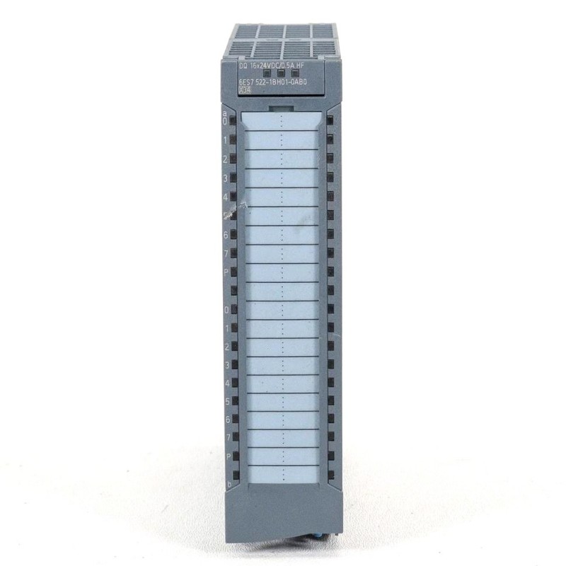
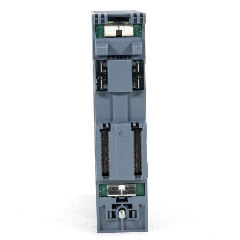
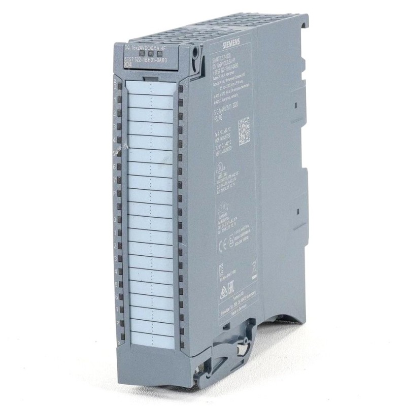
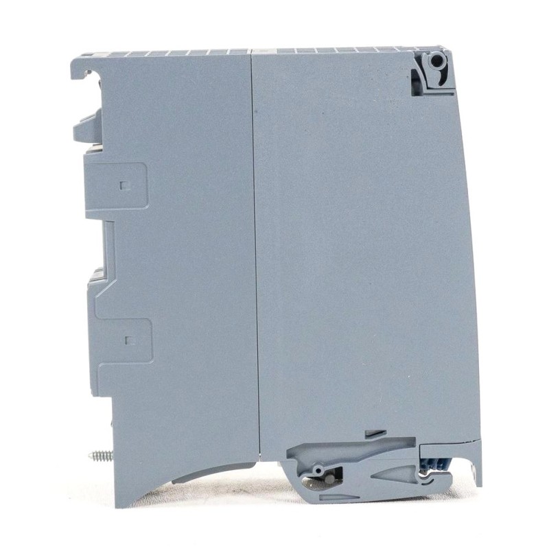
- Siemens
- 6AG1522-1BH01-7AB0
- Digital Output Module
- Germany
- 35 × 147 × 129 mm
- 0.279 kg
- Xiamen, China
- New & In Stock
- T/T, PayPal, Western Union
- 1 Year
- 1-3 Working Days
- DHL, UPS, TNT, FedEx and EMS.
- 24-Hour Service
- COO
- 6
Our advantage

Global Logistics
We have a 10-year logistics and express cooperation agreement, so our products can be shipped to any place in the world.

Brand new and original
Our products are imported in bulk from the place of origin. Because of the cooperative relationship, our products are all original and 100% new.

24-hour service
We provide 7*24 hours service to our customers. We will be there whenever you need us.

Price advantage
All our products are priced very favorably because we have our own warehouse and supply.
| Company Information | |||
| [email protected] | |||
| Mobile | +8615980777398 | ||
| +8615980777398 | |||
| 15980777398 |
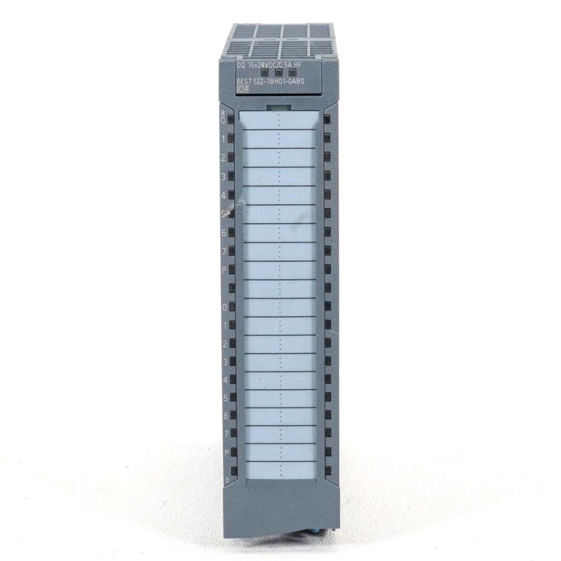
Product Overview
The Siemens 6AG1522-1BH01-7AB0 is a SIPLUS S7-1500 Digital Output Module for adding discrete output channels to an S7-1500 control system operating in demanding industrial environments. It is used when the controller needs to send switching commands to field devices such as contactors, solenoid valves, relays, signal lamps, or other discrete actuators.
Within a typical S7-1500 station, the module receives output states from the CPU through the backplane and converts the controller’s digital commands into corresponding field-side switching signals. This makes it suitable for machine control, process skids, production lines, and distributed automation panels where dependable digital output handling is required.
Technical Specifications
| ParameterSpecification | Value |
|---|---|
| Product Type | SIPLUS S7-1500 Digital Output Module |
| Product Family | SIPLUS S7-1500 |
| Base System | SIMATIC S7-1500 |
| Module Type | Digital Output Module |
| Dimensions | 35 × 147 × 129 mm |
| Weight | 0.279 kg |
Product Features
- Provides discrete output channels for S7-1500 control architectures.
- Converts CPU output commands into field-side switching signals.
- Suitable for controlling relays, contactors, valves, indicators, and other digital actuators.
- Integrates directly into the modular S7-1500 station structure.
- Supports clear separation between controller logic and field-level output devices.
- SIPLUS construction is intended for applications requiring enhanced environmental robustness compared with standard automation hardware.
- Useful for machine and process applications where output switching forms part of the control sequence.
- Supports structured diagnostics and commissioning through the S7-1500 engineering environment.
Working Principle
The 6AG1522-1BH01-7AB0 operates as the output interface between the S7-1500 CPU and connected discrete field devices. The CPU determines the required output states according to the user program, and these states are transferred to the output module through the S7-1500 backplane.
For an energized output, the module switches the corresponding output channel according to the configured output logic. The connected actuator then receives the required electrical signal and changes its operating state. When the CPU removes the command, the output returns to its inactive state.
During commissioning or troubleshooting, the output status can be monitored from the controller and engineering software. This allows technicians to distinguish between a control-program command, an output-channel condition, and a problem further downstream in the field wiring or actuator.
Role in a SIPLUS S7-1500 Control Architecture
| System ElementFunction | |
|---|---|
| S7-1500 CPU | Executes the control program and generates output commands. |
| 6AG1522-1BH01-7AB0 | Converts controller output states into discrete field signals. |
| System Backplane | Transfers power and module data within the S7-1500 station. |
| Digital Field Wiring | Carries switching signals from the module to field devices. |
| Contactors / Relays | Use output commands to switch electrical loads. |
| Solenoid Valves | Convert discrete output commands into pneumatic or hydraulic actions. |
| HMI / Engineering Station | Provides configuration, diagnostics, monitoring, and commissioning functions. |
Industrial Applications
| ApplicationTypical Use | |
|---|---|
| Machine Automation | Switching contactors, relays, lamps, valves, and machine actuators. |
| Production Lines | Controlling discrete devices according to sequential machine logic. |
| Process Skids | Operating pumps, valves, alarms, and auxiliary equipment. |
| Material Handling | Controlling conveyors, diverters, brakes, and signaling devices. |
| Packaging Equipment | Driving actuators and auxiliary switching devices during packaging cycles. |
| Utility Systems | Handling discrete commands for pumps, fans, valves, and alarm circuits. |
| Industrial Control Panels | Providing additional digital output capacity within an S7-1500 station. |
Installation and Maintenance
- Install the module in the designated position within the S7-1500 station and follow the system’s permitted module arrangement.
- Confirm that the hardware configuration matches the actual module installed in the rack.
- Assign the correct output addresses in the PLC engineering project before commissioning field devices.
- Verify terminal assignments carefully before applying field power or connecting actuators.
- Separate output wiring from high-noise power conductors where the cabinet layout permits.
- Check that connected loads are electrically compatible with the output channels and the selected circuit arrangement.
- During commissioning, test individual outputs with the machine in a safe state before enabling automatic sequences.
- Monitor diagnostic information in the engineering environment when an output channel does not respond as expected.
- If an actuator fails to operate, check the PLC command, module status, terminal wiring, field power, and actuator circuit separately.
- Inspect terminals and wiring periodically for looseness, contamination, or signs of overheating.
- Keep the module and surrounding cabinet area within the environmental conditions specified for the SIPLUS system.
- Before replacement, isolate the relevant power sources and verify the hardware configuration so the replacement module is correctly identified by the control system.
Related Components
| ComponentFunction | |
|---|---|
| SIPLUS S7-1500 CPU | Executes application logic and controls the output states. |
| SIPLUS S7-1500 Digital Input Modules | Collect discrete signals from switches and field sensors. |
| SIPLUS S7-1500 Analog Modules | Handle continuous process signals within the same automation station. |
| S7-1500 System Power Components | Support the power architecture of the automation station. |
| SIMATIC S7-1500 Front Connectors | Provide the field wiring interface for compatible modules. |
| Contactors and Relays | Switch higher-power loads from PLC output commands. |
| Solenoid Valves | Perform pneumatic or hydraulic actions initiated by digital outputs. |
| Engineering Software | Used for hardware configuration, programming, monitoring, and diagnostics. |
Recommended Related Models
| Model / Product FamilyProduct Type | Typical Application |
|---|---|
| Siemens SIPLUS S7-1500 Digital Input Modules | Discrete sensor and switch signal acquisition. |
| Siemens SIPLUS S7-1500 Digital Output Modules | Additional discrete actuator control. |
| Siemens SIPLUS S7-1500 Analog Input Modules | Monitoring temperature, pressure, flow, and other analog variables. |
| Siemens SIPLUS S7-1500 Analog Output Modules | Sending continuous control signals to field equipment. |
| Siemens SIPLUS S7-1500 CPU Modules | Central PLC processing and application control. |
| Siemens SIMATIC S7-1500 Communication Modules | Network and system-level communication expansion. |
Key Advantages
- Expands discrete output capacity in a SIPLUS S7-1500 station.
- Fits the modular S7-1500 architecture and engineering workflow.
- Provides a direct interface between PLC logic and discrete actuators.
- Suitable for industrial control panels, machines, and process equipment.
- SIPLUS platform supports applications requiring enhanced environmental suitability.
- Simplifies structured diagnosis of PLC output and field-device control circuits.
Technical FAQs
What types of devices can the 6AG1522-1BH01-7AB0 control?
It can be used for discrete control applications involving compatible field devices such as relays, contactors, solenoid valves, indicator circuits, and other digital actuators.
How is the output module connected to the S7-1500 CPU?
The module communicates with the CPU through the S7-1500 station’s backplane. The CPU transfers the programmed output states to the module, which then controls the corresponding field-side output channels.
What should be checked if an output command is present but the field device does not operate?
Check the PLC output status first, then inspect the module diagnostics, terminal assignment, field power, wiring, actuator circuit, and the actuator itself. Testing these points separately helps identify whether the problem originates in the control program, output module, wiring, or field device.
Can this module be used as an additional output module in an existing S7-1500 station?
Yes, it can be integrated as part of a compatible SIPLUS S7-1500 configuration to increase available digital output capacity. The final configuration should be checked against the station’s CPU, module arrangement, addressing, and system requirements.