

ProductPRODUCT
Featured products
Contact Us
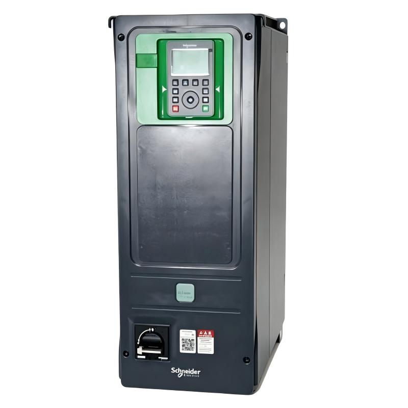
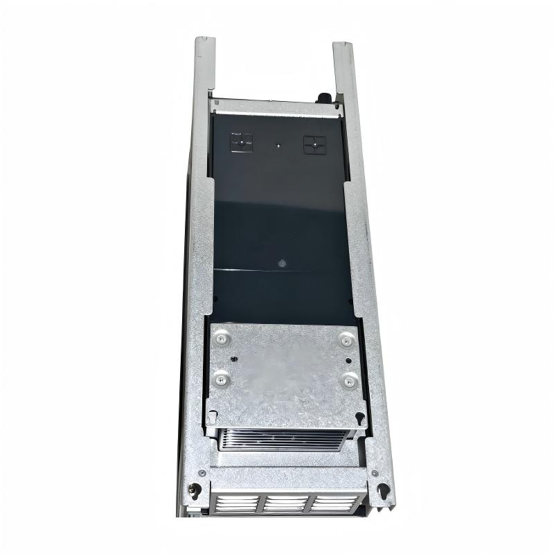
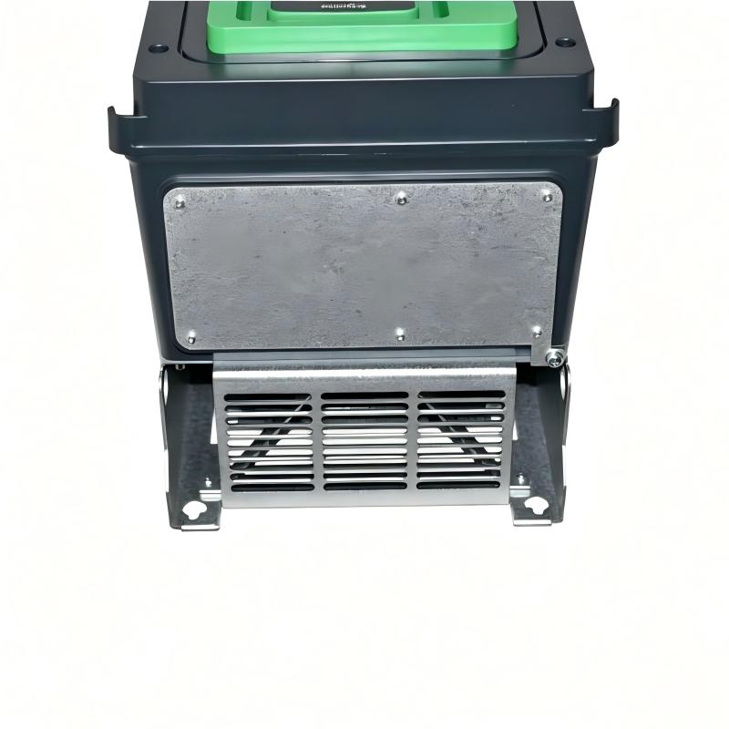
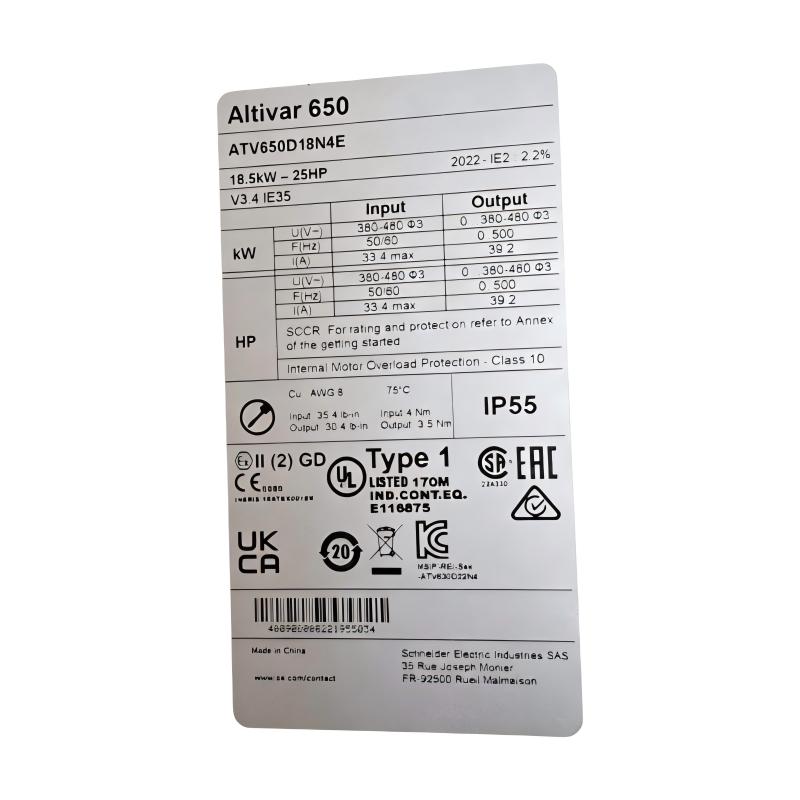
- Schneider
- ATV650D18N4E
- Variable Speed Drive
- France
- 264 x 678 x 330 mm
- 20.6 kg
- Xiamen, China
- New & In Stock
- T/T, PayPal, Western Union
- 1 Year
- 1-3 Working Days
- DHL, UPS, TNT, FedEx and EMS.
- 24-Hour Service
- COO
- 7
Our advantage

Global Logistics
We have a 10-year logistics and express cooperation agreement, so our products can be shipped to any place in the world.

Brand new and original
Our products are imported in bulk from the place of origin. Because of the cooperative relationship, our products are all original and 100% new.

24-hour service
We provide 7*24 hours service to our customers. We will be there whenever you need us.

Price advantage
All our products are priced very favorably because we have our own warehouse and supply.
| Company Information | |||
| [email protected] | |||
| Mobile | +8615980777398 | ||
| +8615980777398 | |||
| 15980777398 |
Product Overview
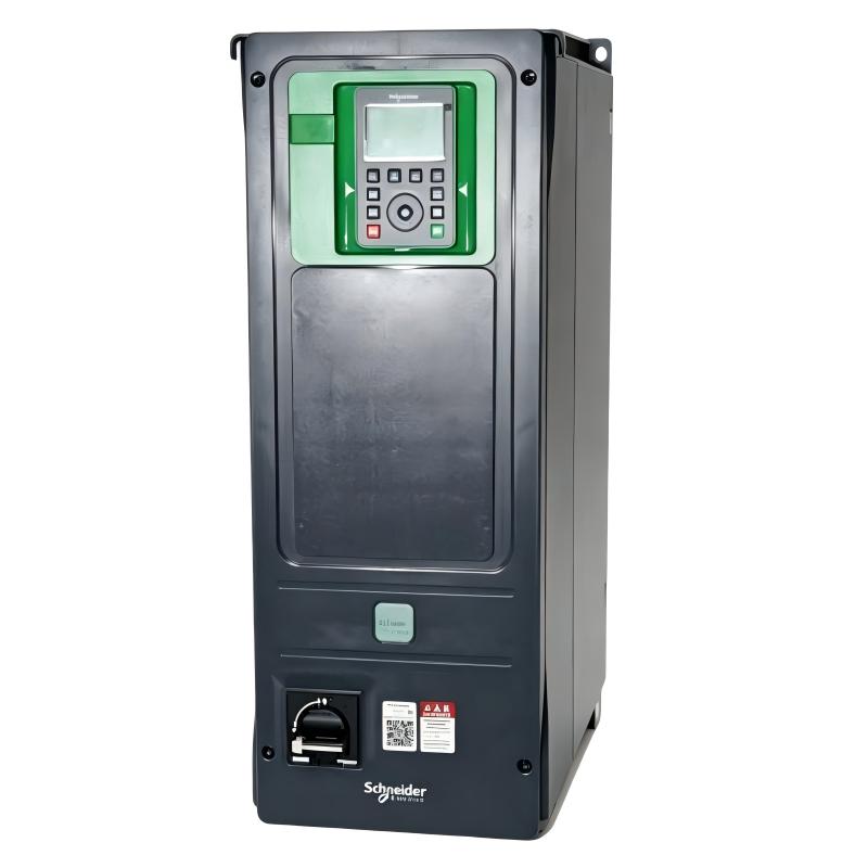
The Schneider Electric ATV650D18N4E Variable Speed Drive is an industrial motor control solution from the Altivar Process ATV650 series, developed for applications requiring reliable variable-speed operation, process optimization, energy management, and integration with modern industrial automation systems. The drive is intended for demanding environments where motor-driven equipment must respond accurately to changing process requirements while maintaining stable and efficient operation.
Variable speed drives are widely used in industrial facilities because many motors do not need to operate continuously at maximum speed. By adjusting motor speed according to actual process demand, a VSD can help improve equipment efficiency, reduce mechanical stress, and provide more precise control of pumps, fans, compressors, and other rotating machinery.
The ATV650D18N4E is particularly suitable for process-oriented applications where motor control is closely associated with production efficiency and equipment monitoring. It can form part of a complete automation architecture involving PLC controllers, HMIs, SCADA systems, process sensors, industrial communication networks, motor protection equipment, and other control components.
For mechanical planning, cabinet design, transportation, and replacement purposes, the supplied physical dimensions of the Schneider ATV650D18N4E are 264 × 678 × 330 mm, with a supplied weight of 20.6 kg.
Technical Specifications
| Parameter | Specification |
|---|---|
| Manufacturer | Schneider Electric |
| Model | ATV650D18N4E |
| Product Series | Altivar Process ATV650 |
| Product Type | Variable Speed Drive / Variable Frequency Drive |
| Application | Industrial motor and process control |
| Motor Type | Three-phase AC motors |
| Drive Category | Process-oriented variable speed drive |
| Primary Function | Motor speed and torque regulation |
| Control Role | Process optimization and motor control |
| Installation | Industrial electrical cabinet / equipment installation |
| Cooling | Forced-air cooling architecture |
| Dimensions | 264 × 678 × 330 mm |
| Weight | 20.6 kg |
| Typical Applications | Pumps, fans, compressors, HVAC, water and wastewater systems |
| Automation Integration | PLC, HMI, SCADA and industrial control systems |
Engineering Specification Note
The exact electrical characteristics of the ATV650D18N4E should be confirmed against the applicable Schneider Electric documentation and the actual hardware configuration before installation. Parameters such as rated motor power, output current, supply voltage, overload capability, braking functions, communication interfaces, control terminals, protection ratings, environmental limits, and application-specific features should not be assumed solely from the model designation.
The dimensions and weight in this article are based on the supplied product information and are intended for mechanical, cabinet, inventory, and logistics planning.
What Is the Schneider ATV650D18N4E?
The Schneider ATV650D18N4E is an Altivar Process Variable Speed Drive designed to control the operating speed and performance of AC motors used in industrial processes.
In a traditional fixed-speed motor installation, the motor is normally operated at a predetermined speed. If the process requires less flow, pressure, airflow, or production capacity, mechanical devices may be used to restrict the output.
A variable speed drive provides a more flexible approach by directly controlling motor operation.
A typical control arrangement can be represented as:
Process Controller → ATV650D18N4E → AC Motor → Driven Equipment
Depending on the application, process sensors can provide feedback to the controller or drive, creating a closed-loop control system.
For example:
Pressure Sensor → Controller → ATV650D18N4E → Pump Motor → Process
The motor speed can then be adjusted according to the actual pressure requirement.
Variable Speed Drive Working Principle
The basic purpose of the ATV650D18N4E is to convert incoming electrical power into a controlled output for an AC motor.
A typical variable speed drive contains several major functional stages.
AC Input Stage
The drive receives electrical power from the plant’s power distribution system.
The incoming power must comply with the electrical requirements of the specific drive configuration.
Rectifier Stage
The incoming AC power is converted into DC power by the drive’s power-conversion circuitry.
DC-Link Stage
The DC-link section provides an intermediate electrical energy stage between the input and inverter sections.
It also contributes to stabilization of the electrical power used by the inverter.
Inverter Stage
The inverter uses high-speed semiconductor switching to generate a controlled AC output.
By modifying the effective output frequency and voltage, the drive can control motor operating conditions.
Motor Control
The drive applies the selected control strategy to regulate motor speed and torque.
The resulting motor operation can then be adjusted to match the process requirement.
This allows the drive to control equipment such as:
- Pumps
- Fans
- Compressors
- Blowers
- Ventilation systems
- Process machinery
- Utility equipment
The actual control performance depends on motor characteristics, drive configuration, load behavior, process requirements, and commissioning parameters.
Role in Industrial Automation Systems
The ATV650D18N4E can function as an intelligent motor-control component within a larger automation architecture.
A typical industrial system may include:
Field Sensors
↓
PLC / Process Controller
↓
Industrial Communication Network
↓
ATV650D18N4E
↓
Motor
↓
Pump / Fan / Compressor / Process Equipment
The drive can participate in several levels of the automation process, including:
- Motor speed control
- Motor starting and stopping
- Process regulation
- Operating-status monitoring
- Fault reporting
- Alarm handling
- Energy management
- Equipment protection
- Remote operation
- Preventive maintenance
This architecture allows the variable speed drive to become part of the overall process-control strategy instead of functioning only as a standalone motor controller.
Energy Efficiency and Process Optimization
Energy efficiency is one of the major reasons for installing variable speed drives in industrial systems.
Many process loads vary throughout the day. A pump, fan, or compressor may require different operating speeds depending on production requirements.
Operating such equipment continuously at maximum speed can result in unnecessary energy consumption.
With variable speed control, the motor can operate closer to the required process point.
For example:
High Process Demand → Higher Motor Speed
Low Process Demand → Lower Motor Speed
This approach can provide substantial energy benefits in suitable variable-torque applications.
The ATV650D18N4E can therefore contribute to:
- Reduced energy consumption
- Improved process efficiency
- Lower operating costs
- Reduced mechanical stress
- More stable process control
- Flexible equipment operation
- Improved motor utilization
Actual energy savings depend on the load profile, motor efficiency, operating hours, mechanical system, and process requirements.
Industrial Applications
Water and Wastewater Treatment
Water-treatment facilities contain numerous motor-driven systems that operate under changing process conditions.
The ATV650D18N4E can be incorporated into applications involving:
- Water pumps
- Booster pumps
- Filtration systems
- Process-water circulation
- Wastewater handling
- Aeration equipment
- Sludge-related equipment
- Cooling-water systems
Variable speed control can help equipment respond to changing flow and pressure requirements.
Pumping Systems
Industrial pumping systems frequently require variable flow rates.
A variable speed drive can regulate pump speed instead of relying exclusively on mechanical throttling.
Applications include:
- Process pumps
- Transfer pumps
- Circulation pumps
- Cooling pumps
- Water supply
- Industrial utility systems
Correct pump selection and drive configuration are important for achieving stable operation.
HVAC and Ventilation
Fans and ventilation systems often experience changing airflow requirements.
The ATV650D18N4E can be incorporated into:
- Industrial ventilation
- Exhaust systems
- Air-handling equipment
- Cooling systems
- Process ventilation
- Building utility systems
Speed control allows airflow to better match actual demand.
Compressor Systems
Industrial compressors can operate under changing production loads.
Variable speed control can help coordinate motor operation with compressor demand where the application is suitable for drive-based control.
Typical applications include:
- Factory compressed-air systems
- Process compressors
- Utility compressors
- Industrial air systems
Compressor applications should be evaluated carefully because acceleration, minimum operating speed, lubrication, and mechanical load characteristics can vary significantly.
Chemical Processing
Chemical processing facilities use motors throughout production and utility systems.
The ATV650D18N4E may be integrated into applications such as:
- Chemical transfer pumps
- Circulation systems
- Cooling systems
- Process ventilation
- Utility equipment
The installation must be evaluated against the specific environmental and safety requirements of the plant.
Food and Beverage Manufacturing
Food and beverage plants use variable-speed equipment in both production and utility applications.
Potential applications include:
- Process pumping
- Water circulation
- Cooling systems
- Ventilation
- Material handling
- Utility equipment
Precise speed control can contribute to more consistent process operation.
Motor Control and Closed-Loop Process Control
The ATV650D18N4E can be used in systems where motor speed is directly related to a process variable.
Consider a pump station where a target pressure must be maintained.
A pressure sensor measures the actual pressure.
The controller compares the measured pressure with the target value.
If pressure falls below the required level, the controller can increase the speed reference.
If pressure becomes higher than required, the controller can reduce the speed reference.
The control loop becomes:
Pressure Transmitter → PLC / Controller → ATV650D18N4E → Pump Motor → Process
The same concept can be applied to:
- Flow control
- Airflow control
- Temperature-related circulation
- Tank-level control
- Pressure regulation
- Process circulation
The exact feedback architecture depends on the system design.
Installation Guidelines
Proper installation is essential for reliable operation of the ATV650D18N4E.
Before installation, engineers should verify:
- Complete drive model
- Electrical supply
- Motor rating
- Motor cable requirements
- Cabinet dimensions
- Cooling requirements
- Ambient conditions
- Grounding
- EMC requirements
- Control wiring
- Communication architecture
- Protective equipment
- Safety circuits
The supplied physical size is:
264 × 678 × 330 mm
The supplied weight is:
20.6 kg
The enclosure should provide sufficient space around the drive for cable installation, ventilation, inspection, and maintenance.
Cabinet and Mechanical Installation
The ATV650D18N4E should be mounted securely according to the applicable Schneider Electric installation requirements.
The cabinet design should provide:
- Adequate mechanical support
- Proper ventilation
- Heat dissipation
- Cable access
- Electrical clearance
- Service access
Variable speed drives generate heat during operation. If the cabinet cannot dissipate this heat effectively, internal temperatures may increase and reduce the expected service life of electronic components.
The installation environment should therefore be evaluated for:
- Ambient temperature
- Dust
- Moisture
- Condensation
- Corrosive substances
- Vibration
- Airflow
Power Wiring
Power wiring should be performed by qualified electrical personnel.
Before energizing the drive, verify that the incoming supply and motor connections are correct.
Important installation considerations include:
- Correct supply configuration
- Appropriate protective devices
- Proper conductor sizing
- Grounding
- Motor cable selection
- Cable routing
- Terminal identification
- Isolation procedures
Power cables should be routed in a controlled manner to reduce electrical interference with instrumentation and communication wiring.
Motor Cable and EMC Considerations
The switching operation of a variable speed drive can generate high-frequency electrical noise.
Correct installation practices can help minimize EMC problems.
Recommended engineering practices include:
- Proper grounding
- Correct motor cable selection
- Shielding where required
- Appropriate shield termination
- Separation of motor and control cables
- Separation from sensitive analog signals
- Proper cabinet bonding
- Suitable EMC accessories where required
The exact EMC requirements should be determined from the installed drive configuration and the electrical standards applicable to the facility.
Control and Communication Integration
The ATV650D18N4E can be integrated into an industrial automation environment where motor operation must be coordinated with PLCs, HMIs, SCADA systems, and process instrumentation.
A typical architecture is:
SCADA / HMI
↓
PLC / Process Controller
↓
Industrial Network
↓
ATV650D18N4E
↓
Motor
↓
Process Equipment
The automation system may exchange information such as:
- Start command
- Stop command
- Speed reference
- Drive status
- Operating condition
- Alarm information
- Fault information
- Process-related data
The exact protocol, communication interface, addressing method, and network configuration should be verified for the specific installation.
Commissioning Procedure
Commissioning should be performed in a controlled and documented manner.
1. Mechanical Inspection
Verify that the drive is securely mounted and that sufficient ventilation and service space are available.
2. Electrical Inspection
Check power wiring, grounding, motor cables, control connections, and protective devices.
3. Motor Parameter Configuration
Enter the required motor nameplate information into the drive.
Do not use estimated motor data when actual nameplate information is available.
4. Control Configuration
Configure the required start, stop, reference, and control functions according to the application.
5. Initial Motor Test
Perform a controlled motor test at a safe operating condition.
Verify motor rotation and abnormal vibration or noise.
6. Acceleration and Deceleration Test
Confirm that the configured acceleration and deceleration behavior is suitable for the connected equipment.
7. Process Test
Gradually increase operating conditions while monitoring motor current, speed, process feedback, and drive status.
8. Alarm and Fault Test
Verify that expected protection and alarm responses operate correctly.
9. Documentation
Record the final drive parameters and commissioning results for future maintenance.
Troubleshooting and Fault Diagnosis
When troubleshooting an ATV650D18N4E installation, the drive should be considered as part of the complete motor-control system.
A fault can originate from:
- Electrical supply
- Motor
- Motor cable
- Mechanical load
- Process equipment
- Sensors
- PLC
- Communication network
- Drive parameters
- Environmental conditions
- Internal electronics
Drive Does Not Start
Check:
- Incoming power
- Start command
- Operating mode
- Active fault status
- Safety circuit
- Speed reference
- Communication command
- Motor configuration
A missing start command should not be mistaken for a failed drive.
Motor Does Not Reach Required Speed
Possible causes include:
- Incorrect reference
- Incorrect motor parameters
- Excessive load
- Process-control limitations
- Communication scaling
- Incorrect configuration
Compare the commanded speed with the actual operating speed.
Drive Trips During Acceleration
Possible causes include:
- Excessive mechanical load
- Acceleration time too short
- Motor problems
- Incorrect configuration
- Power disturbances
- Motor cable problems
The mechanical equipment should be inspected as part of the diagnosis.
Drive Overheats
Potential causes include:
- High ambient temperature
- Poor cabinet ventilation
- Blocked airflow
- Excessive load
- Dust accumulation
- Cabinet thermal-design problems
Cooling performance should be checked before replacing the drive.
Communication Problems
If the drive cannot communicate with the controller, inspect:
- Network cables
- Communication settings
- Address configuration
- Protocol configuration
- Network equipment
- PLC settings
- Drive communication status
Communication problems should be diagnosed separately from power-stage or motor faults.
Preventive Maintenance
A preventive maintenance program can improve the reliability of the ATV650D18N4E and the connected equipment.
Drive Inspection
Inspect the drive and surrounding cabinet for visible abnormalities.
Cooling Inspection
Check ventilation paths and cooling components for dust accumulation or obstruction.
Cable Inspection
Inspect motor and control cables for mechanical damage, loose connections, and environmental deterioration.
Terminal Inspection
Check electrical connections according to the applicable maintenance procedure.
Motor Inspection
Monitor motor temperature, vibration, sound, and mechanical condition.
Fault History Review
Recurring alarms or trips should be investigated rather than simply reset.
Process Trend Monitoring
Monitoring speed, current, pressure, flow, temperature, and other process variables can help identify developing problems.
Replacement and Spare-Part Considerations
When replacing a Schneider ATV650D18N4E, technicians should verify the complete model designation.
Important information includes:
- Full model number
- Hardware identification
- Existing configuration
- Motor nameplate data
- Control mode
- Communication settings
- External accessories
- Safety connections
- Application parameters
The supplied physical specifications are:
264 × 678 × 330 mm
20.6 kg
These specifications should be considered when planning cabinet access, transportation, lifting, and installation.
A replacement should not be selected solely because it has a similar appearance or physical size. Electrical ratings and application requirements must also be confirmed.
Physical Dimensions and Weight
The Schneider ATV650D18N4E has the following supplied mechanical specifications:
| Physical Parameter | Value |
|---|---|
| Height | 678 mm |
| Width | 264 mm |
| Depth | 330 mm |
| Weight | 20.6 kg |
The overall size should be considered together with the required wiring space, ventilation area, mounting hardware, and service clearance.
For large industrial control cabinets, proper mechanical planning is important because insufficient service space can make maintenance and replacement considerably more difficult.
Integration with PLC and SCADA Systems
The ATV650D18N4E can form part of a hierarchical industrial control architecture.
At the field level, sensors monitor process conditions.
At the control level, PLCs or process controllers determine operating commands.
At the drive level, the ATV650D18N4E regulates motor operation.
At the supervisory level, HMI and SCADA systems provide operators with process information.
A simplified architecture is:
Sensors
↓
PLC / Controller
↓
ATV650D18N4E
↓
Motor
↓
Process
↓
Sensors
This architecture creates a continuous information loop between the physical process and the automation system.
Engineering Best Practices
Select the Drive According to the Actual Load
Motor power alone should not be the only consideration. Load characteristics, starting conditions, operating cycle, environmental conditions, and process requirements should also be evaluated.
Maintain Proper Cabinet Cooling
Thermal management is essential for power electronics.
Separate Power and Signal Wiring
Good cable routing can reduce electrical interference.
Document Parameters
Keep a record of commissioning parameters so that troubleshooting and future replacement can be performed efficiently.
Investigate Repeated Faults
Repeated drive trips can indicate an underlying motor, mechanical, electrical, or process problem.
Inspect the Complete System
Do not automatically assume that a drive fault means the drive itself has failed.
Maintain Accurate Spare-Part Information
Record the full model number and system configuration in the plant maintenance database.
Recommended Related Schneider Electric Models
| Model | Product Type | General Application |
|---|---|---|
| ATV650D11N4 | Altivar Process Variable Speed Drive | Industrial process motor control |
| ATV650D11N4E | Altivar Process Variable Speed Drive | Process and industrial applications |
| ATV650D15N4 | Altivar Process Variable Speed Drive | Pumps and process equipment |
| ATV650D18N4 | Altivar Process Variable Speed Drive | Industrial motor speed control |
| ATV650U40N4E | Altivar Process Variable Speed Drive | Utility and process applications |
| ATV650U55N4 | Altivar Process Variable Speed Drive | Industrial process equipment |
| ATV630D37N4 | Altivar Process Variable Speed Drive | Pumps, fans and process systems |
| ATV630D45N4 | Altivar Process Variable Speed Drive | Industrial motor applications |
| ATV630D55N4 | Altivar Process Variable Speed Drive | Larger process equipment |
| ATV630D75N4 | Altivar Process Variable Speed Drive | High-capacity process applications |
These models are related Schneider Electric variable speed drive products, but they should not be considered automatic replacements for the ATV650D18N4E. Electrical ratings, motor requirements, environmental conditions, communication functions, mechanical dimensions, and application requirements should be verified before substitution.
Key Advantages
The Schneider ATV650D18N4E offers several important advantages for industrial motor-control applications:
- Process-oriented variable speed control
- Flexible AC motor speed regulation
- Potential energy savings in suitable variable-load applications
- Reduced mechanical stress during controlled starting and stopping
- Integration into industrial automation architectures
- Suitable for pump and fan applications
- Support for process monitoring
- Industrial diagnostic capabilities
- Flexible PLC and SCADA integration
- Suitable for demanding process environments
- 264 × 678 × 330 mm supplied dimensions
- 20.6 kg supplied weight
Technical FAQs
What is the Schneider ATV650D18N4E?
The Schneider Electric ATV650D18N4E is an Altivar Process ATV650 Variable Speed Drive designed for industrial motor speed and process-control applications.
What is the primary function of the ATV650D18N4E?
Its primary function is to regulate the operation of AC motors so that motor speed and performance can be adjusted according to process requirements.
What applications can use the ATV650D18N4E?
Typical applications include industrial pumps, fans, compressors, HVAC systems, water and wastewater equipment, chemical-processing systems, and other process machinery.
What are the dimensions of the ATV650D18N4E?
The supplied dimensions are 264 × 678 × 330 mm.
What is the weight of the ATV650D18N4E?
The supplied product weight is 20.6 kg.
Can the ATV650D18N4E be integrated with a PLC?
Yes, the drive can form part of an industrial automation architecture involving PLCs, HMIs, SCADA systems, and other control equipment. The exact communication configuration should be confirmed for the specific installation.
Can a variable speed drive reduce energy consumption?
Yes. In suitable applications, particularly variable-torque pump and fan systems, reducing motor speed can significantly reduce energy consumption compared with continuous full-speed operation.
Why does a variable speed drive trip during acceleration?
Possible causes include excessive mechanical load, unsuitable acceleration settings, motor problems, incorrect parameters, power disturbances, or motor cable issues. The drive diagnostic information should be reviewed before replacing hardware.
What should be checked before replacing an ATV650D18N4E?
Verify the complete model number, motor data, electrical supply, application requirements, control configuration, communication settings, safety connections, accessories, and mechanical installation requirements.
Is the ATV650D18N4E suitable for water and wastewater applications?
The ATV650 process-drive family is designed for industrial process applications and can be incorporated into suitable water and wastewater motor-control systems. Final suitability depends on the complete installation and environmental requirements.
How can the service life of the drive be improved?
Good cabinet ventilation, appropriate electrical installation, clean cooling paths, proper grounding, correct motor parameters, regular inspection, and investigation of recurring faults can all contribute to reliable long-term operation.
Conclusion
The Schneider Electric ATV650D18N4E Variable Speed Drive is an industrial motor-control solution designed for applications where flexible speed regulation, process optimization, energy management, and automation integration are important. As part of the Altivar Process ATV650 series, it can be incorporated into motor-driven systems involving pumps, fans, compressors, HVAC equipment, water-treatment machinery, and other industrial process equipment.
By controlling motor speed according to actual process demand, the ATV650D18N4E can help improve process stability, reduce unnecessary energy consumption, and minimize mechanical stress in suitable applications. Its role can extend beyond basic motor starting and stopping to include integration with PLCs, SCADA systems, process sensors, and industrial communication architectures.
For mechanical planning and replacement logistics, the supplied dimensions are 264 × 678 × 330 mm, while the supplied weight is 20.6 kg. These specifications should be considered when designing electrical cabinets, planning installation space, arranging transportation, and preparing maintenance procedures.
Reliable operation depends on correct drive selection, proper electrical and mechanical installation, accurate motor parameterization, appropriate cooling, effective grounding, suitable EMC practices, and regular preventive maintenance. Before installing or replacing the ATV650D18N4E, engineers and maintenance personnel should verify the complete model designation and all application-specific electrical and control requirements.