
NewsNEWCENTER
Featured products
Contact Us
Allen-Bradley 1402-LS51 Line Synchronization Module Fault Diagnosis Guide
2026-06-23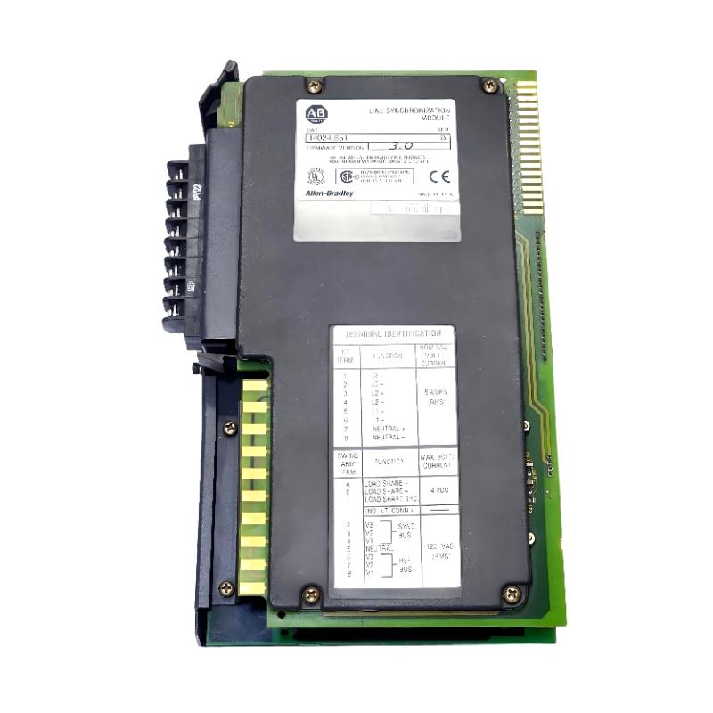
Table of Contents
- Field Case: Breaker Refuses to Close During Generator Synchronization
- Fault Symptoms of 1402-LS51 Module
- Observed Phase Angle & Voltage Mismatch Behavior
- Root Cause Analysis (CT/PT Error & Signal Processing Deviation)
- Diagnostic Workflow for Synchronization System
- Repair & Recovery Actions
- Prevention Strategy for Synchronization Systems
- FAQs on 1402-LS51 Faults
- Engineering Summary
Field Case: Generator Fails to Parallel with Utility Grid
Allen-Bradley 1402-LS51 line synchronization module faults often present as failed breaker closure during generator-to-grid synchronization. In one power plant scenario, operators observed repeated synchronization attempts without successful breaker closure, despite apparently stable voltage and frequency matching on the HMI.
Fault Symptoms of 1402-LS51 Module
Typical field symptoms include:
- Breaker close command blocked during sync sequence
- Persistent phase angle mismatch alarm
- Unstable frequency slip readings
- Incorrect voltage comparison between buses
Observed Phase Angle & Voltage Mismatch Behavior
During commissioning diagnostics, engineers observed inconsistent synchronization measurements:
GRID_VOLTAGE = stable
GENERATOR_VOLTAGE = stable
FREQUENCY_SLIP = fluctuating (±0.3 Hz)
PHASE_ANGLE_ERROR = oscillating near threshold limit
SYNC_PERMISSION = repeatedly denied
BREAKER_STATUS = remains OPEN
Despite stable raw electrical values, the module continuously failed synchronization validation due to internal measurement inconsistency.
Root Cause Analysis (CT/PT Error & Signal Processing Deviation)
The 1402-LS51 relies on accurate CT/PT inputs and precise phase calculation algorithms. Common failure mechanisms include:
- Incorrect CT polarity causing inverted phase detection
- PT scaling mismatch leading to voltage comparison errors
- Signal noise affecting phase angle calculation stability
- Aging input conditioning circuits introducing measurement drift
In one field case, reversed CT wiring on a single phase caused continuous 180° phase error detection, fully blocking synchronization.
Diagnostic Workflow for Synchronization System
A structured electrical verification process is required:
- Verify CT/PT polarity and secondary wiring integrity
- Measure real phase rotation using external analyzer
- Compare module readings with independent measurement tools
- Check signal conditioning board for drift or noise influence
- Review PLC block transfer data consistency
SYNC_DIAG /MODEL=1402-LS51 /PHASE_VERIFY /CT_POLARITY_CHECK /VOLTAGE_COMPARE
Repair & Recovery Actions
- Corrected CT polarity and rewired affected phase inputs
- Recalibrated PT scaling parameters in configuration table
- Replaced noisy signal conditioning interface module
- Validated synchronization sequence with external analyzer
After correction, synchronization succeeded within acceptable phase tolerance and breaker closed normally under load conditions.
Prevention Strategy for Synchronization Systems
- Always verify CT/PT polarity during commissioning
- Perform dual-instrument phase verification before sync enable
- Maintain shielding for all analog measurement wiring
- Regularly validate calibration drift in long-term operation
- Avoid relying solely on single-module readings for critical decisions
FAQs on 1402-LS51 Faults
Why does synchronization fail even when voltage and frequency look correct?
Because phase angle or CT/PT scaling errors can still violate internal synchronization thresholds.
Can wiring errors cause permanent sync blocking?
Yes. Incorrect CT polarity or phase rotation errors will continuously prevent breaker closure.
Is the module always faulty in sync failure cases?
No. Most failures are caused by external wiring, configuration, or measurement issues rather than hardware failure.
Engineering Summary
The Allen-Bradley 1402-LS51 line synchronization module is highly dependent on accurate analog measurement inputs and correct system configuration. Field failures are most often caused by CT/PT wiring errors, phase mismatch, or signal conditioning drift rather than internal module defects. Proper diagnostic separation between field wiring and module logic is essential for reliable synchronization performance.