
NewsNEWCENTER
Featured products
Contact Us
Allen-Bradley 1336F-MCB-SP1J Drive Control Board Fault Diagnosis Guide
2026-06-22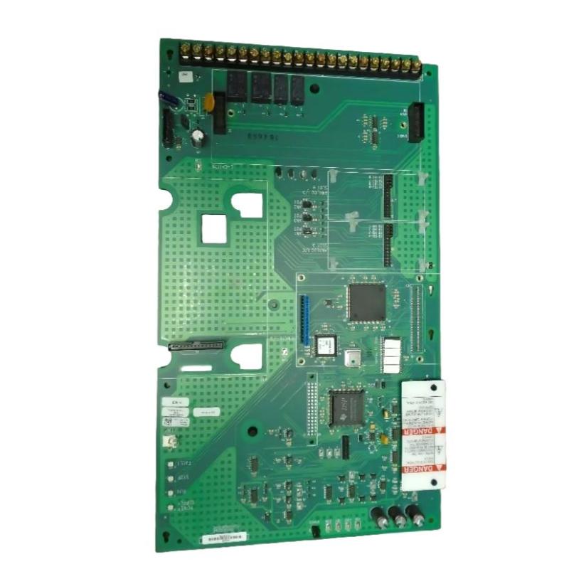
Table of Contents
- Field Case: 1336F Drive No-Start Condition with Healthy Power Stage
- Fault Symptoms of 1336F-MCB-SP1J Control Board
- Observed Control Logic Failure & Signal Loss Patterns
- Root Cause Analysis (CPU Logic Fault & Feedback Loop Disruption)
- Diagnostic Workflow for Drive Control Board
- Repair & Recovery Actions
- Prevention Strategy for 1336F Series Drives
- FAQs on 1336F-MCB-SP1J Faults
- Engineering Summary
Field Case: 1336F Drive Powers On But Never Runs
Allen-Bradley 1336F-MCB-SP1J drive control board faults often appear as a “no-run” condition where the drive powers up normally, DC bus is stable, but no inverter switching occurs. In one conveyor system, operators reported repeated start commands with no motor response, despite all power components testing healthy.
Fault Symptoms of 1336F-MCB-SP1J Control Board
Typical field symptoms include:
- Drive powers ON but refuses RUN command execution
- No PWM output despite valid control input
- Display and keypad functional but no motor response
- Intermittent communication timeout with external controller
Observed Control Logic Failure & Signal Loss Patterns
Engineering diagnostics revealed missing internal enable signals between logic layers:
RUN_COMMAND = accepted at keypad
INTERNAL_ENABLE = not asserted
PWM_GENERATION = blocked
FAULT_OUTPUT = intermittent or none
DC_BUS = stable (no collapse)
DRIVE_STATE = READY but not RUNNING
This pattern indicates a control layer breakdown rather than a power stage or inverter fault.
Root Cause Analysis (CPU Logic Fault & Feedback Loop Disruption)
The 1336F-MCB-SP1J control board manages sequencing, protection logic, and PWM generation. Common failure mechanisms include:
- Microcontroller degradation due to thermal aging
- EEPROM corruption affecting startup logic parameters
- Faulty opto-isolation between control and feedback circuits
- Voltage ripple impacting logic stability under load transitions
In one field case, repeated undervoltage events corrupted startup parameters, leaving the drive stuck in READY state indefinitely.
Diagnostic Workflow for Drive Control Board
A structured control-level isolation process is required:
- Verify DC bus and low-voltage supply rails
- Check keypad and external run command input signals
- Monitor internal status LEDs for logic progression
- Test communication link with PLC or controller
- Inspect control board for thermal or capacitor degradation
CONTROL_BOARD_DIAG /MODEL=1336F-MCB-SP1J /LOGIC_CHECK /PWM_ENABLE_TEST /STATE_MACHINE_VERIFY
Repair & Recovery Actions
- Replaced corrupted control board EEPROM or entire MCB module
- Restored factory parameters and startup configuration
- Re-seated ribbon connectors between logic and power boards
- Stabilized auxiliary control power supply rails
After correction, the drive successfully entered RUN state and restored full PWM output under load.
Prevention Strategy for 1336F Series Drives
- Avoid repeated undervoltage or unstable power conditions
- Perform periodic backup of drive parameters
- Ensure proper cooling for control electronics section
- Minimize electrical noise coupling into control circuits
- Inspect connectors during preventive maintenance cycles
FAQs on 1336F-MCB-SP1J Faults
Why does the drive power up but not run?
This usually indicates a control logic failure preventing PWM generation, not a power stage issue.
Can parameter corruption stop the drive from starting?
Yes. Corrupted EEPROM or startup configuration can block the internal enable sequence.
Is replacing the control board always required?
Not always, but in most field cases involving logic failure, replacement is the most reliable solution.
Engineering Summary
The Allen-Bradley 1336F-MCB-SP1J drive control board is the core logic controller of the 1336F series VFD. Failures are typically related to control firmware corruption, signal isolation issues, or aging electronic components rather than power stage faults. Accurate diagnosis requires separating logic-level behavior from inverter hardware performance.