
NewsNEWCENTER
Featured products
Contact Us
Allen-Bradley 1747-M11 SLC 500 Flash Memory Module – Installation, Setup and Commissioning Guide
2026-11-11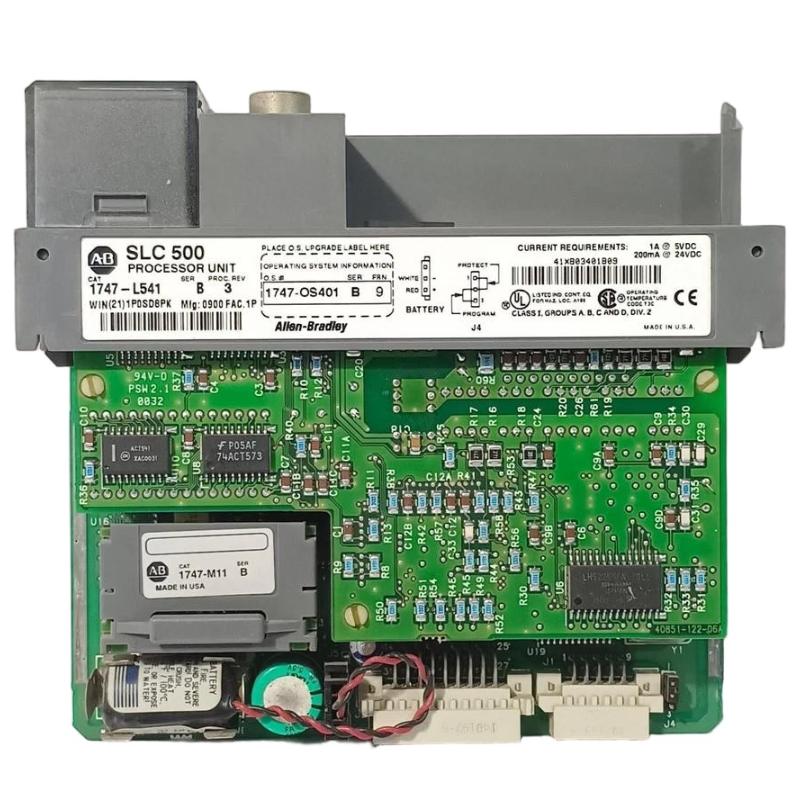
1. Introduction
The Allen-Bradley 1747-M11 is a removable Flash EPROM memory module designed for compatible SLC 500 programmable logic controllers. It provides non-volatile storage for user programs and data, allowing an application program to be preserved independently of the processor’s working memory.
In industrial automation systems, maintaining a reliable copy of the control program is essential for equipment recovery, controller replacement, and maintenance operations. The 1747-M11 provides a portable memory solution that can be used to store a backup of the SLC 500 application and restore it to a compatible processor when required.
The module is associated with SLC 5/03, SLC 5/04, and SLC 5/05 processor families, but compatibility depends on the memory module series and processor operating system revision. The Series A and Series B versions do not have identical compatibility requirements. Therefore, identifying the exact module revision is an essential part of installation and commissioning.
2. Product Overview
The 1747-M11 belongs to the Allen-Bradley SLC 500 memory module family. It uses Flash EPROM technology and supports up to 32K of user memory backup. It is designed to preserve a controller program and associated data for later loading into compatible processor memory.
Unlike an ordinary I/O module, the 1747-M11 does not directly process field input signals or switch field output devices. Its primary role is program storage and recovery. The module is installed in the designated memory module socket of a compatible SLC 500 processor.
Key Functions
- Stores a backup copy of the SLC 500 user program.
- Provides non-volatile program storage.
- Supports program transfer and recovery procedures.
- Allows stored application programs to be used as a recovery source.
- Supports write-protection options for stored programs.
- Provides a removable memory solution for maintenance and controller replacement.
3. Technical Specifications
| Parameter | Specification |
|---|---|
| Manufacturer | Allen-Bradley / Rockwell Automation |
| Catalog number | 1747-M11 |
| Product family | SLC 500 |
| Module type | Flash Memory Module |
| Memory technology | Flash EPROM |
| Memory backup capacity | Up to 32K of user memory |
| Supported processor families | Selected SLC 5/03, SLC 5/04, and SLC 5/05 processors |
| Module versions | Series A and Series B |
| Programming interface | Compatible SLC 500 processor and programming software |
| External programming adapter | 1747-M15 for compatible PROM programmer applications |
| Primary application | Program backup, storage, and recovery |
The 1747-M11 is commonly described as supporting up to 32K of user memory backup. Some product listings use different memory terminology or provide inconsistent capacity figures. For technical selection, use the processor compatibility table and memory capacity information in the applicable SLC 500 documentation.
4. Processor Compatibility and Revision Identification
Compatibility is one of the most important considerations when selecting an 1747-M11. The module’s series determines which SLC 500 processors and operating system revisions can use it.
| Memory Module | Compatible Processor | Required Operating System |
|---|---|---|
| 1747-M11 Series A | SLC 5/03 | OS300 or OS301 |
| 1747-M11 Series A | SLC 5/04 | OS400 |
| 1747-M11 Series B | SLC 5/03 | OS302 or higher |
| 1747-M11 Series B | SLC 5/04 | OS401 or higher |
| 1747-M11 Series B | SLC 5/05 | Supported SLC 5/05 processors |
Before installation, inspect the label on the memory module and record its series. Then identify the processor catalog number and operating system revision. Do not assume that every SLC 5/03 or SLC 5/04 processor supports every 1747-M11 revision.
The 1747-M11 should also not be confused with the 1747-M12 or 1747-M13. These are different memory module models with different capacity and compatibility characteristics.
5. Installation Preparation
5.1 Verify the Existing Controller
Identify the SLC 500 processor installed in the control system. Record the complete catalog number, processor series, and operating system revision. This information is required to confirm compatibility with the 1747-M11.
5.2 Inspect the Memory Module
Check the module housing, connector, and identification label. Look for cracks, deformation, contamination, corrosion, or damaged connector contacts.
Do not install a module with visible physical damage. A damaged connector may prevent reliable electrical contact or cause problems during program transfer.
5.3 Prepare a Verified Program Backup
Before making changes to the controller, upload and save the existing application program using the appropriate programming software. Confirm that the saved file is the correct project and that it represents the intended operating configuration.
Where applicable, record the processor configuration, data tables, communication settings, and other information required for recovery. A memory module should not be treated as the only backup copy of an important industrial control application.
5.4 Prepare the Work Area
Perform the installation in a clean, dry, and controlled environment. Use ESD protection when handling the module and avoid touching its electrical contacts unnecessarily.
Confirm that the machine or process is in a safe maintenance condition before changing processor memory or initiating a program transfer.
6. Physical Installation Procedure
Step 1: Confirm Processor Compatibility
Check the processor model and operating system against the compatibility information for the exact 1747-M11 series. If the processor revision is unknown, identify it through the controller’s diagnostic or programming interface before proceeding.
Step 2: Place the Controller in a Safe Condition
Notify the relevant operations personnel and follow the site’s maintenance and lockout/tagout procedures. A memory operation can affect the program used to control machinery, so ensure that the process is in an approved condition.
Step 3: Locate the Memory Module Socket
Identify the designated memory module socket on the SLC 500 processor. Refer to the processor hardware documentation for the exact location and installation orientation.
Step 4: Inspect the Connector
Check the processor socket for dust, foreign material, corrosion, or mechanical damage. Do not use excessive force or insert the memory module at an angle.
Step 5: Install the 1747-M11
Align the module connector with the processor memory socket and insert it according to the processor manufacturer’s instructions. Confirm that it is fully seated and mechanically secure.
Step 6: Verify the Installation
Inspect the installed module and confirm that it is correctly positioned. If the module does not fit easily, stop and recheck the orientation and compatibility rather than forcing the connector.
7. Memory Configuration and Program Preparation
7.1 Understand the Memory Module Configuration
The SLC 500 processor uses memory configuration settings to determine how the memory module participates in program backup and startup operations. These settings must be reviewed before programming or restoring the 1747-M11.
For applicable SLC 500 processors, the memory module configuration bits include S:1/10 through S:1/12. Their settings should be established in the offline project according to the intended memory module operation and processor documentation.
7.2 Verify the Offline Project
Open the correct controller project in the compatible programming software. Check the processor type, application program, data tables, and memory configuration settings.
Confirm that the project is intended for the target processor. A program prepared for a different processor type or operating system may not be suitable for transfer.
7.3 Download the Program to the Processor
Where the selected backup procedure requires it, download the verified application program to the target SLC 500 processor. Follow the programming software instructions and confirm that the processor accepts the program without errors.
7.4 Burn the Program to the Flash Memory Module
After the controller contains the intended program, use the applicable programming software procedure to transfer the program into the 1747-M11. Follow the exact software prompts for memory module programming.
Do not interrupt the transfer process. An incomplete programming operation may leave the stored application unusable or inconsistent with the intended project.
7.5 Verify the Stored Program
After programming, verify that the memory operation has completed successfully. Where supported, perform the recommended verification or comparison procedure to confirm that the stored program matches the intended application.
8. Program Backup and Recovery Procedure
8.1 Creating a Backup
For routine program protection, use the approved programming software to create a verified copy of the application in the 1747-M11.
A practical backup workflow includes:
- Upload the current processor program.
- Save an offline copy with a clear project name and date.
- Verify the processor catalog number and operating system.
- Review the memory module configuration bits.
- Transfer the intended program to the memory module.
- Confirm successful completion.
- Record the module series and the application revision.
8.2 Restoring a Program
When a controller program must be recovered, first verify that the processor is compatible with the installed 1747-M11. Confirm that the stored application is the correct version for the machine or process.
Follow the processor-specific instructions for loading the program from the memory module. Pay attention to the processor’s memory module configuration and startup behavior.
8.3 Verify the Recovered Application
After recovery, check the controller’s operating mode, program status, I/O configuration, communication settings, and relevant data tables. Confirm that the application is the intended revision before allowing normal machine operation.
Test the system under controlled conditions and obtain the required operational authorization before returning the equipment to service.
9. Write Protection and Program Security
Flash EPROM technology provides the ability to preserve stored programs and supports write-protection options. Depending on the programming method and system configuration, the program may be protected through software settings or compatible PROM programming equipment.
Before enabling write protection, verify that the stored application is correct and that a separate verified backup exists. Write protection should be managed according to the site’s program-change and maintenance procedures.
Do not attempt to bypass protection or modify memory settings without authorization. Uncontrolled changes to a controller program can affect machine behavior and process reliability.
10. Troubleshooting and Maintenance
10.1 Processor Does Not Recognize the Memory Module
Possible causes include an incompatible module series, unsupported processor operating system, incorrect installation orientation, damaged connector contacts, or a defective memory module.
Check the processor catalog number, operating system revision, module series, and physical connection before considering replacement.
10.2 Program Cannot Be Transferred to the Module
Check the programming software procedure, processor compatibility, program configuration, and memory module condition. Confirm that the processor contains the intended application and that the memory configuration settings are correct.
10.3 Controller Does Not Start with the Expected Program
Check whether the memory module contains the correct program and whether the processor is configured to use it as intended. Review the startup behavior and memory configuration instructions for the exact SLC 500 processor.
10.4 Stored Program Is Not the Latest Revision
Compare the memory module backup with the approved offline project. A memory module may contain an older application if it has not been updated after the latest program changes.
Maintain revision records for every backup operation. Clearly identify the program version, machine or system, and backup date.
10.5 Physical Damage or Unreliable Connection
Inspect the housing and connector contacts. If the module has damaged components, corrosion, or persistent connection problems, replace it with a compatible unit rather than attempting an undocumented repair.
11. Technical FAQs
1. What is the Allen-Bradley 1747-M11 used for?
The 1747-M11 is a Flash EPROM memory module used with compatible SLC 500 processors to store and back up user programs and associated data.
2. Which PLC family uses the 1747-M11?
It is designed for selected Allen-Bradley SLC 500 processors, including compatible SLC 5/03, SLC 5/04, and SLC 5/05 models. Exact compatibility depends on the module series and processor operating system.
3. What is the memory capacity of the 1747-M11?
The module supports up to 32K of user memory backup. Check the applicable processor documentation when evaluating program size and memory requirements.
4. What is the difference between 1747-M11 Series A and Series B?
The main distinction is processor and operating system compatibility. Series A supports earlier specified SLC 5/03 and SLC 5/04 revisions, while Series B supports later SLC 5/03 and SLC 5/04 revisions and compatible SLC 5/05 processors.
5. Can the 1747-M11 be used with an SLC 5/05 processor?
The Series B 1747-M11 is listed for compatible SLC 5/05 processors. Do not assume that Series A has the same compatibility.
6. Is the 1747-M11 an ordinary EEPROM module?
It is identified as a Flash EPROM memory module for the SLC 5/03, SLC 5/04, and SLC 5/05 processor family. It should not be confused with the earlier 1747-M1 and 1747-M2 EEPROM modules.
7. What is the 1747-M15 used for?
The 1747-M15 is an adapter socket used when programming compatible memory modules with a commercial PROM programmer. It is not the same product as the 1747-M11.
8. Can the 1747-M11 restore a controller program?
Yes, it can serve as a program backup and recovery source when used with a compatible processor and the correct memory configuration procedure.
9. Should the 1747-M11 be the only backup of a PLC program?
No. Maintain a separate verified offline project file and appropriate revision records. Multiple backup copies reduce the risk of losing an important control application.
10. What should be checked before replacing an existing 1747-M11?
Check the module series, processor catalog number, operating system revision, program capacity requirements, and the compatibility of the replacement module. Also verify that the replacement contains the intended program if it is being used for recovery.
12. Technical Summary
The Allen-Bradley 1747-M11 SLC 500 Flash Memory Module is a removable non-volatile memory device designed to preserve user programs and data for compatible SLC 5/03, SLC 5/04, and SLC 5/05 controllers. It supports up to 32K of user memory backup and is available in Series A and Series B versions with different processor compatibility requirements.
Successful installation and operation depend on confirming the processor model, operating system revision, memory module series, and program configuration. A verified backup, correct memory configuration, careful programming procedure, and post-recovery testing are essential for reliable use in industrial automation systems.