
NewsNEWCENTER
Featured products
Contact Us
Allen-Bradley 1734-OB8 POINT I/O 8-Point Digital Output Module Troubleshooting and Fault Diagnosis Guide
2026-11-11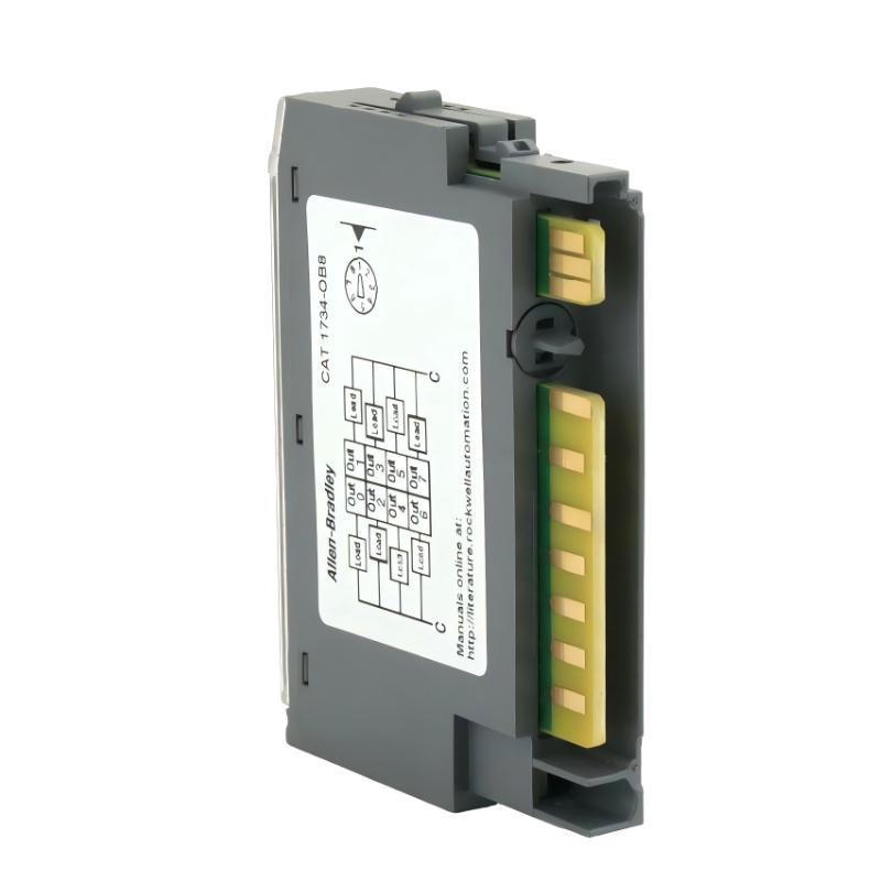
1. Introduction
The Allen-Bradley 1734-OB8 is an eight-channel digital DC output module belonging to the POINT I/O product family. It provides eight non-isolated sourcing outputs for controlling compatible 24V DC field devices, including indicator lamps, interposing relays, solenoid valves, and other industrial control loads.
When the module experiences an operating problem, typical symptoms include inactive output channels, unexpected output behavior, intermittent load operation, module status faults, or network communication errors. These symptoms may originate from the module itself, the terminal base, external field power, wiring, connected loads, or controller configuration.
This guide explains how to identify common faults, interpret status indicators, inspect the output circuits, diagnose communication problems, and determine when module replacement is necessary. The procedures are intended for qualified industrial automation maintenance personnel.
2. Understanding the 1734-OB8 Before Troubleshooting
Before diagnosing a fault, it is important to understand the module’s output arrangement and electrical characteristics.
| Parameter | Specification |
|---|---|
| Manufacturer | Allen-Bradley |
| Model | 1734-OB8 |
| Product family | POINT I/O |
| Module type | 8-Point Digital DC Output Module |
| Output channels | 8 |
| Output type | Non-isolated sourcing |
| Nominal output voltage | 24V DC |
| On-state voltage range | 10–28.8V DC |
| Maximum on-state voltage drop | 0.2V DC |
| Maximum current per channel | 1.0 A |
| Maximum total module current | 3.0 A |
| Maximum off-state leakage current | 0.5 mA |
| Maximum output delay | 0.1 ms |
| POINTBus current consumption | 75 mA maximum at 5V DC |
| Compatible terminal bases | 1734-TB and 1734-TBS |
The standard 1734-OB8 must not be confused with the 1734-OB8E or other protected output variants. Their diagnostic and protection functions are not necessarily identical. Always identify the exact catalog number and series before applying a troubleshooting procedure.
3. Common Fault Symptoms
3.1 All Eight Outputs Are Inactive
If none of the output channels operates, investigate shared power and control conditions before assuming that all eight output circuits have failed.
Possible causes include:
- Missing POINT I/O station power.
- Incorrect or missing field-side DC supply.
- Incorrect common or return wiring.
- Module not fully seated in the terminal base.
- Communication adapter or network fault.
- Incorrect controller I/O configuration.
- Controller logic not issuing the expected output commands.
3.2 One Output Channel Does Not Operate
If only one channel is inactive, inspect its assigned output tag, terminal connection, field conductor, and connected load. A defective field device or open circuit may produce the same symptom as a failed module channel.
3.3 Output Indicator Is On but the Load Does Not Work
The output indicator represents the logical output state. It does not independently prove that the external load is receiving the correct voltage or that the load itself is functional.
Possible causes include a missing 24V DC supply, incorrect wiring, an open conductor, a failed field device, or a problem with the module’s output circuit.
3.4 Load Remains Energized After the Output Command Turns Off
If the field device remains energized when the controller removes the output command, investigate the output circuit for wiring errors, unintended parallel supply paths, or a damaged output stage.
Isolate the circuit before disconnecting conductors or testing the output. Do not rely on the PLC command alone to establish that the load is de-energized.
3.5 Module Status Indicator Shows a Fault
A red or flashing status indicator may indicate a recoverable or unrecoverable module condition. The exact meaning depends on the indicator pattern. Record the state and review the controller diagnostics before replacing the module.
3.6 Network Status Indicator Shows a Communication Problem
A network indicator fault may prevent the controller from exchanging output data with the POINT I/O station. Check the communication adapter, network cabling, node configuration, and I/O connection status.
4. Interpreting the Module Status Indicators
The 1734-OB8 provides module status, network status, and output status indications. Correct interpretation helps narrow down the source of a fault.
4.1 Module Status Indicator
| Indicator State | Meaning | Recommended Action |
|---|---|---|
| Off | No power applied to the device | Check station power and module installation |
| Green | Device operating normally | No action required if other diagnostics are normal |
| Flashing green | Missing, incomplete, or incorrect configuration | Review module configuration and commissioning |
| Flashing red | Recoverable fault | Review controller diagnostics and correct the reported condition |
| Red | Unrecoverable fault; replacement may be required | Check the system and module diagnostics before replacement |
| Flashing red/green | Device in self-test mode | Allow the self-test to complete and check whether normal operation returns |
4.2 Network Status Indicator
| Indicator State | Meaning | Recommended Action |
|---|---|---|
| Off | Device is not online or has not completed its duplicate-node-address test | Check power, adapter, and network configuration |
| Flashing green | Device is online but connections are not established | Check controller configuration and I/O connection setup |
| Green | Device is online with established connections | Normal communication status |
| Flashing red | One or more I/O connections have timed out | Check network stability and controller connection status |
| Red | Critical communication link failure | Inspect the communication adapter and network path |
| Flashing red/green | Communication-faulted state | Review network access and communication diagnostics |
4.3 Output Status Indicators
The 1734-OB8 front panel provides output indicators for the eight channels. The indicator arrangement groups the visual indications for outputs 0 and 4, 1 and 5, 2 and 6, and 3 and 7.
| Indicator State | Meaning |
|---|---|
| Off | The corresponding output channel is inactive. |
| Yellow | The corresponding output channel is active and under control. |
Unlike certain protected POINT I/O output modules, the standard 1734-OB8 should not be assumed to provide the same open-load and short-circuit diagnostic indications. Do not interpret flashing red or steady red output indications documented for the 1734-OB8E as standard 1734-OB8 channel diagnostics.
5. Safety Precautions Before Troubleshooting
The 1734-OB8 controls external DC field circuits. Some connected loads may also be associated with machinery capable of unexpected movement or process activation.
- Follow the site’s lockout/tagout procedure before handling field wiring.
- Identify and isolate the POINT I/O power source and relevant external field supplies.
- Verify the absence of hazardous voltage with suitable test equipment.
- Discharge stored energy in connected equipment according to the equipment manufacturer’s instructions.
- Use ESD precautions when handling the module.
- Do not disconnect safety-related or process-critical signals without authorization.
- Never exceed the specified output current or voltage limits during testing.
- Use appropriately rated test equipment and insulated tools.
6. Step-by-Step Troubleshooting Procedure
Step 1: Identify the Fault and Record Its Conditions
Begin by determining whether the fault affects the complete module, a group of channels, or one specific output.
Record the following information:
- Module catalog number and series.
- POINT I/O station and module position.
- Controller output tag or address.
- Module and network status indicator states.
- Output indicator state for the affected channel.
- External field supply voltage.
- Connected load type and rated current.
- Controller diagnostic messages and fault history.
- Recent wiring, configuration, or equipment changes.
Recording these details helps distinguish a controller command problem from an external circuit or module fault.
Step 2: Check the Module Status Indicator
Inspect the module status indicator and compare its state with the table in Section 4. If the indicator is off, verify the station power supply and module installation.
If it flashes green, check whether the module has been correctly added to the POINT I/O configuration. If it flashes red or remains red, review the controller’s diagnostic information to identify the reported condition.
Step 3: Check Network Communication
Inspect the network status indicator and confirm that the POINT I/O station is online.
If the network indicator is off, check the communication adapter, station power, network cable, and node configuration. If it flashes green, the device may be online without an established I/O connection. Verify that the controller project and communication adapter configuration match the installed station.
If the network indicator flashes red, investigate connection timeouts, network interruptions, and controller communication status. A network fault may prevent otherwise functional output hardware from receiving valid commands.
Step 4: Verify the Controller Output Command
Open the controller project and monitor the output tag associated with the affected channel. Confirm that the program logic is issuing the intended on/off command.
Check:
- Output tag assignment.
- Module position and I/O mapping.
- Program interlocks and permissive conditions.
- Controller operating mode.
- Communication connection status.
- Fault or idle-state output configuration.
If the controller is not commanding the output, investigate the program logic and process conditions before inspecting the physical output circuit.
Step 5: Check the External 24V DC Supply
The 1734-OB8 uses a sourcing output arrangement. When a channel is commanded on, it supplies positive DC voltage to the connected load. The load return must be connected to the correct DC common reference.
Check the external supply and common wiring using the approved electrical test procedure. Confirm that the supply remains within the specified 10–28.8V DC on-state voltage range.
Also inspect the power distribution arrangement. The module’s internal power bus and the field-side common arrangement must be correctly supplied through the applicable adapter, field potential distributor, extension power supply, or approved auxiliary terminal arrangement.
Step 6: Inspect the Affected Output Channel
Observe the output indicator while monitoring the controller command.
- If the controller command is off and the indicator is off, the channel is responding consistently with the command.
- If the controller command is on and the indicator remains off, investigate the I/O configuration, communication connection, and module condition.
- If the command is on and the indicator is yellow, continue with external circuit testing if the load does not operate.
Because the standard module’s output indicators show logical channel status rather than complete load-circuit health, additional electrical measurements are necessary.
Step 7: Inspect Field Wiring and Terminal Connections
With the relevant circuit isolated, inspect the terminal base and field wiring. Look for loose conductors, damaged insulation, incorrect polarity, corrosion, contamination, and signs of overheating.
Confirm that each load is connected to the correct output terminal and that its return conductor reaches the correct DC common. Compare the physical wiring with the approved electrical drawings.
Step 8: Measure the Output Circuit
Qualified technicians can measure the voltage at the output and load terminals using suitable test equipment and an approved test procedure.
When the output is commanded on, verify that the voltage available to the load is consistent with the field supply and load requirements. The maximum specified on-state voltage drop across the output is 0.2V DC under the stated conditions.
If the output command and indicator are correct but the load voltage is absent or significantly lower than expected, inspect the supply, wiring, terminal connections, and output channel. Avoid shorting terminals or using an unsuitable test load.
Step 9: Check Load Current
The maximum output current is 1.0 A per channel, with a maximum combined current of 3.0 A for the complete module.
Calculate the current of all simultaneously operating loads. A module may experience problems even when no individual channel exceeds 1.0 A if the combined load exceeds the 3.0 A module limit.
Also consider inrush current and inductive load characteristics. If a connected device requires more current than the module can provide, use an appropriately rated interposing relay or external switching device.
Step 10: Inspect Inductive Loads and Suppression Components
Solenoid valves, relay coils, and other inductive loads can generate transient voltages when switched off. Inspect any external suppression components for incorrect selection, damaged wiring, or failure.
Verify that the suppression arrangement is suitable for the load voltage and required release time. Do not assume that the standard 1734-OB8 has the same built-in electronic protection features as protected output variants.
Step 11: Check the Terminal Base and POINTBus Connection
If several channels behave abnormally or the module intermittently disappears from the controller configuration, inspect the terminal base and POINTBus connection.
Look for poor mechanical engagement, damaged contacts, contamination, and incorrect installation. Check adjacent modules and station power distribution if other modules report similar symptoms.
Step 12: Perform a Controlled Channel Comparison
Where permitted by the process and wiring design, compare the affected channel with another known-good channel operating a compatible load.
Use this comparison to identify whether the problem follows the field device, the wiring, the controller tag, or the module channel. Do not interchange conductors while energized, and do not connect a load to a different output without confirming the electrical design.
7. Troubleshooting Reference Table
| Fault Symptom | Possible Cause | Recommended Action |
|---|---|---|
| Module status indicator off | No station power or poor module installation | Check power distribution and terminal base engagement |
| Module status flashing green | Missing or incorrect configuration | Verify module identity and controller configuration |
| Module status flashing red | Recoverable module fault | Review controller diagnostics and correct the reported issue |
| Module status red | Unrecoverable module fault | Verify system conditions and consider replacement |
| Network status off | Station offline or network initialization problem | Check adapter power, network connection, and node configuration |
| Network status flashing green | No established I/O connection | Check controller and adapter I/O configuration |
| Network status flashing red | I/O connection timeout | Investigate network interruptions and connection status |
| All outputs inactive | Missing power, communication fault, or absent output commands | Check station power, field supply, network, and controller logic |
| One output inactive | Incorrect tag, loose wire, or defective field load | Check the affected channel and external circuit |
| Output indicator yellow but load inactive | Missing field supply, open wiring, or output circuit problem | Measure the load circuit and inspect terminal connections |
| Intermittent load operation | Unstable supply, loose connection, or excessive load demand | Inspect wiring, supply quality, and current consumption |
| Load remains energized | Output circuit damage or unintended external supply path | Isolate the circuit and investigate the physical wiring |
8. Repair and Replacement Recommendations
8.1 When the Problem Is in the External Circuit
If testing identifies a missing field supply, damaged cable, loose terminal, incorrect common connection, or defective load, repair the external circuit rather than replacing the I/O module unnecessarily.
After completing the repair, repeat the output test and verify that the connected load operates correctly.
8.2 When Module Replacement Is Necessary
Replacement should be considered when a confirmed internal module fault remains after checking power, network communication, controller configuration, terminal base condition, and external wiring.
Typical reasons for replacement include:
- Unrecoverable module status fault.
- Physical damage to the module.
- Confirmed output channel failure.
- Abnormal operation that remains after external circuit faults are eliminated.
8.3 Replacement Compatibility Checks
Before installing another module, confirm the exact catalog number, series, terminal base compatibility, output arrangement, and controller configuration.
Do not treat the 1734-OB8E, 1734-OB8K, or 1734-OB8EK as automatically interchangeable with the standard 1734-OB8. Differences in protection, diagnostics, and installation requirements must be evaluated.
8.4 Post-Replacement Testing
After replacement, verify that the module is correctly seated, recognized by the controller, and operating with normal module and network status indications.
Test all eight output channels individually. Confirm output polarity, field load operation, and current consumption. Finally, perform a representative combined-load test without exceeding the module’s electrical ratings.
9. Preventive Maintenance Recommendations
- Inspect terminal base connections and field wiring during scheduled maintenance.
- Check the external 24V DC supply for stability and correct polarity.
- Monitor the total output load and individual channel current.
- Inspect connected solenoid valves, relay coils, and other inductive loads.
- Check external suppression components where fitted.
- Review controller diagnostics and network connection history.
- Keep module configuration and electrical drawings up to date.
- Maintain suitable cabinet temperature and environmental conditions.
- Record recurring faults and replacement history for trend analysis.
10. Frequently Asked Questions
1. Why does the 1734-OB8 have no output even though the controller is running?
The controller may not be issuing the required output command, or the POINT I/O station may have a communication or configuration problem. Check the controller output tag, module status, network status, and field-side supply.
2. What does a green module status indicator mean?
A steady green module status indicator means the device is operating normally. It does not independently confirm that every output load and field connection is functioning correctly.
3. What does a flashing green module status indicator mean?
It indicates that the module requires commissioning because its configuration is missing, incomplete, or incorrect. Review the module configuration in the controller project.
4. Why is the network status indicator flashing red?
This indicates that one or more I/O connections have timed out. Check the communication adapter, network condition, controller connection, and I/O configuration.
5. Why is the output indicator on but the field device does not operate?
The indicator shows the output command state, not the complete electrical condition of the field circuit. Check the external supply, common wiring, output terminal, load, and current requirements.
6. Can the 1734-OB8 drive a 24V DC solenoid valve?
Yes, provided the valve’s electrical requirements are compatible with the module. Check the coil current, inrush characteristics, and need for external suppression before connection.
7. What is the maximum output current of the module?
The maximum current is 1.0 A per channel and 3.0 A for the module as a whole. Both limits must be respected.
8. Does the standard 1734-OB8 provide open-load and short-circuit diagnostics?
Do not assume it provides the same channel-level open-load and short-circuit indications as the protected 1734-OB8E. Confirm the diagnostic capabilities of the exact catalog number.
9. Can a faulty output channel be repaired in the field?
Field maintenance should focus on checking wiring, power, loads, and configuration. If an internal output channel failure is confirmed, replacing the module with a compatible unit is generally the more appropriate maintenance approach.
10. What should be checked after replacing the module?
Verify module recognition, module and network status, all eight output commands, field wiring, load operation, and total current consumption before returning the system to service.
11. Technical Summary
The Allen-Bradley 1734-OB8 POINT I/O 8-Point Digital Output Module provides eight non-isolated sourcing outputs for 24V DC industrial automation applications. Its maximum output current is 1.0 A per channel, with a maximum combined module current of 3.0 A.
Effective fault diagnosis requires checking module status, network communication, controller output commands, external field power, terminal connections, and connected load characteristics. The module’s output indicators show logical output states and should not be treated as proof of field-load operation.
A systematic troubleshooting process helps maintenance personnel distinguish external wiring and configuration problems from genuine hardware failures. Correct electrical loading, compatible terminal bases, careful commissioning, and regular inspection all contribute to reliable operation of Allen-Bradley POINT I/O systems.