
NewsNEWCENTER
Featured products
Contact Us
Allen-Bradley 1734-OB8 POINT I/O 8-Point Digital Output Module – Installation, Setup and Commissioning Guide
2026-11-11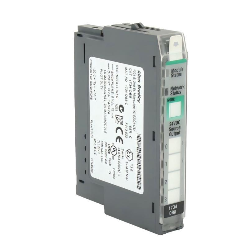
1. Introduction
The Allen-Bradley 1734-OB8 is an eight-channel digital DC output module in the POINT I/O family. Designed for 24V DC industrial control applications, it provides sourcing outputs for switching compatible field devices such as indicator lamps, interposing relays, solenoid valves, and other DC loads.
As part of a distributed I/O architecture, the 1734-OB8 can be installed in a POINT I/O station and controlled by a compatible controller through the station’s communication adapter. Its compact design supports applications where multiple output signals must be distributed close to machinery, equipment, or process devices.
Correct installation requires attention to the terminal base, field-side power supply, output polarity, load current, POINTBus power requirements, and controller configuration. This guide explains the main preparation, wiring, configuration, testing, and commissioning procedures for the 1734-OB8.
2. Product Overview
The 1734-OB8 provides eight non-isolated sourcing digital output channels arranged in one group. Each output switches a positive DC supply to its connected load when commanded by the controller.
The module is designed for a nominal 24V DC operating environment. Its output voltage range is 10–28.8V DC. Each channel supports up to 1.0 A, subject to a maximum combined module current of 3.0 A.
The module is installed on a compatible POINT I/O wiring base assembly. The 1734-TB and 1734-TBS terminal bases are specified for this module. The terminal base provides the field wiring interface, while the module connects to the POINTBus through the installed assembly.
Key Product Characteristics
- Eight digital DC sourcing output channels.
- Nominal operating voltage of 24V DC.
- Output voltage range of 10–28.8V DC.
- Maximum output current of 1.0 A per channel.
- Maximum combined output current of 3.0 A per module.
- Eight yellow output-status indicators.
- Two green/red module and network status indicators.
- Maximum POINTBus current consumption of 75 mA at 5V DC.
- Compatible with specified 1734-TB and 1734-TBS wiring bases.
3. Technical Specifications
| Parameter | Specification |
|---|---|
| Manufacturer | Allen-Bradley |
| Catalog number | 1734-OB8 |
| Product family | POINT I/O |
| Module type | Digital DC Output Module |
| Number of outputs | 8 |
| Output arrangement | One group of 8, non-isolated |
| Output type | Sourcing |
| Nominal voltage | 24V DC |
| Operating voltage range | 10–28.8V DC |
| Maximum on-state voltage drop | 0.2V DC |
| Minimum on-state current | 1.0 mA per channel |
| Maximum off-state leakage current | 0.5 mA |
| Maximum output current | 1.0 A per channel |
| Maximum module output current | 3.0 A total |
| Surge current | 2 A for 10 ms, repeatable every 3 seconds |
| Output signal delay | Maximum 0.1 ms, off-to-on and on-to-off |
| POINTBus current consumption | 75 mA maximum at 5V DC |
| Maximum power dissipation | 2.0 W at 28.8V DC |
| Maximum thermal dissipation | 6.8 BTU/hr |
| Compatible terminal bases | 1734-TB or 1734-TBS |
| Terminal base screw torque | 0.8 N·m (7 lb-in) |
| Operating temperature | -20 to 55°C |
Electrical ratings and terminal assignments should always be checked against the documentation for the exact module series and terminal base. Do not apply specifications for the electronically protected 1734-OB8E or other POINT I/O variants to the standard 1734-OB8.
4. Installation Preparation
4.1 Confirm the Module and Terminal Base
Before installation, verify that the product label identifies the module as 1734-OB8. Check the series, physical condition, terminal base type, and compatibility with the existing POINT I/O station.
The 1734-OB8 is designed for use with the specified 1734-TB or 1734-TBS wiring base assembly. Confirm that the terminal base is correctly installed and that its mechanical connections are undamaged.
4.2 Review the Electrical Design
Prepare the wiring diagram before connecting field devices. Identify the 24V DC supply, common reference, individual output channels, load current, and protective devices.
Calculate the total current expected when all relevant outputs are active. The load must remain within both the 1.0 A per-channel limit and the 3.0 A total module limit.
4.3 Check Cabinet and Environmental Conditions
Install the POINT I/O station in a suitable industrial enclosure. Provide sufficient space for wiring, module removal, ventilation, and maintenance access.
Keep the module away from excessive heat, moisture, conductive dust, and sources of electrical interference. Confirm that the cabinet environment remains within the specified operating temperature range.
5. Mechanical Installation
Step 1: Isolate the Equipment
Before installing the module or handling field wiring, isolate the relevant power sources according to the plant’s lockout/tagout procedure. Verify that the field-side supply and any connected load circuits are de-energized.
Step 2: Install the POINT I/O Terminal Base
Mount the compatible terminal base on the approved DIN rail or POINT I/O mounting arrangement. Confirm that the base is securely positioned and aligned with adjacent modules and the communication adapter.
Step 3: Check the Base Connections
Inspect the POINTBus and mechanical connection areas. Remove dust, foreign material, and any obstruction that could prevent proper module engagement. Do not install a terminal base with damaged contacts or locking features.
Step 4: Mount the 1734-OB8 Module
Align the 1734-OB8 with the terminal base and install it according to the manufacturer’s mechanical instructions. Confirm that the module is fully seated and secured.
Do not force the module into position. Resistance during installation may indicate incorrect alignment, an incompatible base, or damaged mechanical components.
6. Field Wiring and Electrical Connections
6.1 Understand Sourcing Output Operation
The 1734-OB8 uses sourcing outputs. When an output is commanded on, the channel supplies positive DC voltage to the connected load. The load’s return side must be connected to the appropriate DC common reference.
This arrangement is commonly used with compatible DC loads and devices designed for positive-side switching. Verify the electrical input requirements of each connected device before wiring.
6.2 Connect the External DC Supply
Provide a suitable external 24V DC field supply for the output circuits. Confirm that the supply voltage remains within the module’s specified operating range of 10–28.8V DC.
Check supply polarity and common wiring carefully. Incorrect polarity or an unsuitable common arrangement may prevent outputs from operating correctly or damage connected equipment.
6.3 Connect the Output Loads
Connect each field load to its assigned output terminal using the terminal assignment information for the exact module and terminal base. Follow the approved wiring diagram rather than relying on assumptions about terminal position.
Typical connected devices include:
- 24V DC indicator lamps.
- Interposing relay coils.
- Solenoid valves with compatible DC coils.
- DC control inputs on compatible equipment.
- Other low-voltage DC actuators and control devices.
6.4 Verify Current Requirements
Each output channel supports a maximum current of 1.0 A, but the combined current of all active outputs must not exceed 3.0 A for the module.
For example, a design using several output channels must be evaluated by adding their expected simultaneous load currents. A channel operating below 1.0 A does not automatically mean the overall module loading is acceptable.
Consider startup current, coil inrush, switching frequency, and the electrical characteristics of inductive loads. If the load requires more current than the module can provide, use an appropriately rated interposing device or a separate power switching arrangement.
6.5 Tighten Terminal Connections
Use the specified terminal base screw torque of 0.8 N·m (7 lb-in). Avoid overtightening, which may damage the terminal or conductor. Also avoid loose connections, which can cause voltage drops, intermittent operation, and overheating.
6.6 Review Inductive Load Protection
Relay coils, solenoid valves, and other inductive loads can generate voltage transients when switched off. Evaluate the need for suitable external suppression components based on the load manufacturer’s recommendations and the control-system design.
Choose suppression components that are compatible with the DC supply, switching characteristics, and required release time of the load. Do not assume that the standard 1734-OB8 provides the same electronic protection features as the 1734-OB8E.
7. POINT I/O Network and Controller Configuration
7.1 Confirm the Communication Adapter
The 1734-OB8 operates as part of a POINT I/O station. The communication adapter connects the station to the control network and exchanges I/O data with the controller.
Verify that the adapter, network configuration, and controller project support the installed module and its position in the station.
7.2 Configure the I/O Module in the Engineering Software
In the controller project, identify the POINT I/O station and add or verify the 1734-OB8 at the correct module position. Confirm the module catalog number and the station’s I/O arrangement.
Depending on the controller and network architecture, the module may be represented through the communication adapter’s I/O configuration. Follow the applicable controller and adapter instructions.
7.3 Assign Output Tags
Map the eight output points to the appropriate control tags or program addresses. Use clear names that identify the equipment controlled by each channel.
For example, an application may assign separate tags to a pump permissive relay, a valve solenoid, a status lamp, and other control devices. Confirm that the software mapping matches the physical wiring schedule.
7.4 Review Output Data and Fault Behavior
Check the controller’s output data configuration and the module’s communication status. Where the system supports configurable fault or idle behavior, review the selected state for each output and confirm that it is appropriate for the process.
Do not assume that outputs will automatically enter a safe condition after every communication or controller fault. The required behavior must be assessed and configured as part of the machine or process safety design.
8. Commissioning and Functional Testing
Step 1: Inspect the Completed Installation
Before applying power, inspect the terminal base, module seating, wiring, DC supply polarity, conductor routing, and protective devices. Confirm that no loose strands or exposed conductors can create an unintended short circuit.
Step 2: Restore Power
Restore the POINT I/O station and field-side power supplies according to the approved startup sequence. Observe the module and network status indicators.
If a module or network status indicator reports a fault, investigate the station configuration, communication adapter, power distribution, and module seating before proceeding.
Step 3: Check the Output Indicators
The 1734-OB8 has eight yellow output-status indicators. Each indicator provides a visual indication of the corresponding output command state.
Compare the indicator state with the controller’s output data. An illuminated output indicator does not by itself prove that the field load is receiving the correct voltage or operating properly.
Step 4: Test Each Output Individually
Where process conditions permit, command each output on and off under controlled conditions. Observe the corresponding indicator and verify the operation of the connected load.
Test one channel at a time initially. This makes it easier to identify incorrect wiring, unexpected load behavior, and output address mismatches.
Step 5: Verify Voltage at the Load
Use suitable test equipment to verify the voltage at the field device during the commanded on and off states. Compare the measured values with the device’s electrical requirements and the system wiring diagram.
Remember that the module’s maximum on-state voltage drop is 0.2V DC under the specified conditions. Additional voltage loss may occur in field wiring, terminals, protective devices, or external connections.
Step 6: Perform a Combined Load Test
After individual channel checks, test the outputs under representative operating conditions. Confirm that the combined current does not exceed 3.0 A and that no individual channel exceeds 1.0 A.
Monitor the field supply and wiring for abnormal voltage drop or heating. Do not perform overload testing beyond the documented module limits.
Step 7: Confirm Controller Communication
Verify that the controller receives the expected module and network status information. Check for I/O connection faults, configuration mismatches, or unexpected output behavior during normal program execution.
9. Troubleshooting During Installation
| Observed Condition | Possible Cause | Recommended Check |
|---|---|---|
| Module does not appear in the I/O station | Incorrect configuration, poor seating, or communication issue | Check module position, terminal base, adapter, and controller project |
| Module status indicates a fault | Station configuration or module connection problem | Review controller diagnostics and POINT I/O status |
| Output indicator does not turn on | Output command absent or incorrect tag mapping | Check controller logic and output data |
| Indicator is on but load is inactive | Missing field supply, wiring fault, or load problem | Measure the field circuit and inspect the load |
| Output operates intermittently | Loose terminal, unstable supply, or excessive load demand | Check connections and supply stability |
| Several outputs fail together | Shared supply or common wiring problem | Inspect field-side power distribution |
| Module operates but controller reports I/O errors | Network or configuration mismatch | Check adapter status and I/O configuration |
10. Maintenance and Replacement
10.1 Routine Inspection
Include the 1734-OB8 in the site’s scheduled control-system inspection program. Check terminal tightness, conductor condition, module seating, cabinet cleanliness, and the condition of the external 24V DC supply.
Review the load current of connected devices whenever field equipment is changed. Replacing a small indicator with a higher-current device, for example, may affect the output loading calculation.
10.2 Replacing the Module
Before replacement, isolate the relevant power sources and verify that the equipment is safe to handle. Record the module catalog number, series, station position, terminal base type, and existing wiring arrangement.
Install a replacement 1734-OB8 or an explicitly approved alternative. Do not assume that a similarly named module has identical protection, diagnostics, wiring, or output characteristics.
10.3 Verify Operation After Replacement
After installation, restore power according to the approved procedure. Confirm that the module is recognized by the controller, that network and module status indicators are normal, and that all eight output channels operate as expected.
Complete individual and combined load tests before returning the equipment to normal service.
11. Frequently Asked Questions
1. What type of module is the Allen-Bradley 1734-OB8?
It is an eight-channel POINT I/O digital DC output module with sourcing outputs designed for 24V DC industrial control applications.
2. How many output channels does the 1734-OB8 provide?
The module provides eight non-isolated sourcing output channels arranged in one group.
3. What is the operating voltage range?
The specified on-state voltage range is 10–28.8V DC, with a nominal operating voltage of 24V DC.
4. What is the maximum current per output?
Each output supports up to 1.0 A, subject to the maximum combined module current of 3.0 A.
5. Which terminal bases are compatible with the 1734-OB8?
The specified terminal base assemblies include the 1734-TB and 1734-TBS. Confirm the exact base and wiring arrangement before installation.
6. What does a yellow output indicator mean?
It indicates the logical status of the corresponding output point. It does not independently confirm that the field load is receiving power or operating correctly.
7. Can the 1734-OB8 control solenoid valves?
Yes, it can control compatible 24V DC solenoid loads when their current and switching characteristics remain within the module’s electrical limits. External suppression may be required for inductive loads.
8. What is the maximum total output current?
The combined output current must not exceed 3.0 A across the module, even when individual channels are each below their 1.0 A limit.
9. Is the 1734-OB8 the same as the 1734-OB8E?
No. They are different catalog numbers. The 1734-OB8E includes electronic protection features that should not be assumed to exist on the standard 1734-OB8.
10. What should be checked if an output indicator is on but the field device does not work?
Check the external DC supply, field wiring, load polarity, protective devices, and the electrical condition of the connected device. Also verify that the load current is within the module’s limits.
12. Technical Summary
The Allen-Bradley 1734-OB8 POINT I/O 8-Point Digital Output Module provides eight non-isolated sourcing outputs for 24V DC industrial control systems. It supports an operating voltage range of 10–28.8V DC, a maximum current of 1.0 A per channel, and a maximum combined module current of 3.0 A.
Successful installation depends on using a compatible POINT I/O terminal base, providing a suitable external field supply, observing output polarity, and correctly configuring the module in the controller project. During commissioning, each output should be tested individually and then under representative combined load conditions. Proper wiring, load assessment, and periodic inspection help maintain reliable operation in distributed industrial automation systems.