

ProductPRODUCT
Featured products
Contact Us
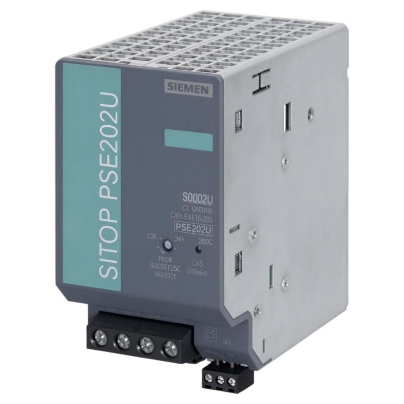
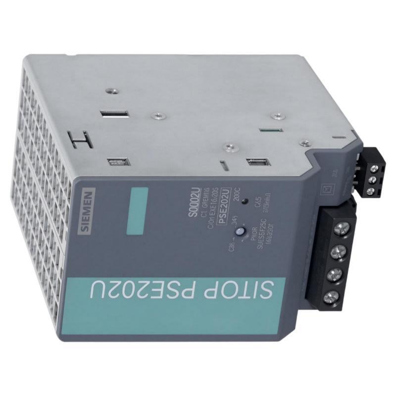
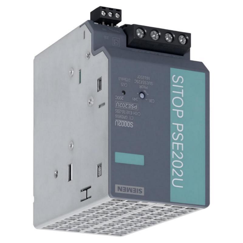
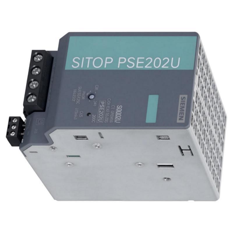
- Siemens
- 6AG1961-3BA21-4AX0
- Redundancy Module
- Germany
- 138 x 150 x 80 mm
- 0.483 kg
- Xiamen, China
- New & In Stock
- T/T, PayPal, Western Union
- 1 Year
- 1-3 Working Days
- DHL, UPS, TNT, FedEx and EMS.
- 24-Hour Service
- COO
- 3
Our advantage

Global Logistics
We have a 10-year logistics and express cooperation agreement, so our products can be shipped to any place in the world.

Brand new and original
Our products are imported in bulk from the place of origin. Because of the cooperative relationship, our products are all original and 100% new.

24-hour service
We provide 7*24 hours service to our customers. We will be there whenever you need us.

Price advantage
All our products are priced very favorably because we have our own warehouse and supply.
| Company Information | |||
| [email protected] | |||
| Mobile | +8615980777398 | ||
| +8615980777398 | |||
| 15980777398 |
Product Overview
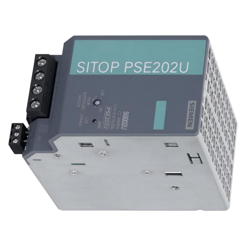
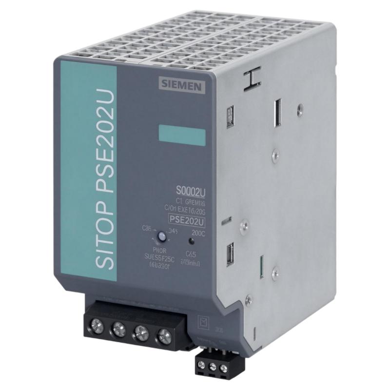
The Siemens 6AG1961-3BA21-4AX0 SIPLUS PS E202U Redundancy Module is designed to improve the availability of 24 V DC power systems used in industrial automation and control applications. It allows two independent SITOP power supplies to operate in a redundant arrangement by electrically decoupling their outputs and combining them into a shared DC supply system.
This module is based on the standard Siemens 6EP1961-3BA21 redundancy module and belongs to the SIPLUS product range. It features conformal coating, making it suitable for industrial environments where electronic assemblies may be exposed to environmental stresses beyond those normally encountered in standard control cabinets.
The module supports a 24 V DC output system with a maximum aggregate output current of 40 A. It is designed to decouple two SITOP power supplies, each with a maximum output current of 20 A. If one power supply becomes unavailable, the other can continue supplying the connected load, provided that the remaining supply has sufficient capacity.
Redundant power arrangements are particularly important in industrial facilities where control-system interruptions can affect production, equipment availability, and process stability. PLC systems, industrial communication devices, control panels, and other 24 V DC equipment often require a dependable power source.
The 6AG1961-3BA21-4AX0 helps reduce the risk of a single power-supply failure interrupting the entire DC distribution system. It does not replace the power supplies themselves; instead, it provides the isolation and combining function needed for a properly designed redundant power architecture.
Technical Specifications
| Parameter | Specification |
|---|---|
| Brand | Siemens |
| Product Range | SIPLUS |
| Model | 6AG1961-3BA21-4AX0 |
| Product Name | SIPLUS PS E202U Redundancy Module |
| Product Type | DC Power Redundancy Module |
| Base Model | 6EP1961-3BA21 |
| Input Voltage | 24 V DC |
| Input Voltage Range | 24–28.8 V DC |
| Output Voltage | 24 V DC nominal |
| Maximum Output Current | 40 A |
| Redundant Power Supply Configuration | 2 × 20 A maximum |
| Output Voltage Characteristics | Controlled, isolated DC output |
| Typical Output Voltage Drop | Approximately 0.5 V |
| Efficiency | Approximately 96.6% |
| Typical Power Loss at Rated Load | 34 W |
| Maximum No-Load Power Loss | 1.5 W |
| Operating Temperature | 0 to +60°C |
| Protection Rating | IP20 |
| Electrical Connection | Screw terminals |
| Mounting Type | DIN rail mounting |
| Coating | Conformal coating |
| Dimensions Provided | 138 × 150 × 80 mm |
| Weight Provided | 0.483 kg |
| Typical Application | Redundant 24 V DC industrial power distribution |
Note: Dimensions and weight are the supplied product-listing values. Confirm the manufacturer’s mechanical drawing and the actual unit before panel design or shipping calculations.
Function and Working Principle
The primary function of the 6AG1961-3BA21-4AX0 is to create a redundant 24 V DC power arrangement by isolating two independent power-supply outputs from each other while feeding a common load.
In an industrial control system, a single power supply can become a critical point of failure. If that supply stops operating, connected controllers, sensors, communication equipment, and other devices may lose power. A redundancy module helps address this risk by allowing two power supplies to support the same load.
1. Dual Power Supply Decoupling
The module accepts two 24 V DC input sources. Each source is supplied by an independent SITOP power supply with a maximum output current of 20 A.
The module electrically decouples the two inputs. This prevents one power supply from directly feeding back into the output of the other supply if their output voltages differ or one source fails.
The two sources then support a shared output rated for a maximum aggregate current of 40 A.
This arrangement is commonly used in industrial control cabinets where continuous DC power is important.
2. Redundant Power Operation
Under normal operating conditions, both connected power supplies can contribute to the common DC power system.
If one power supply fails or its output voltage drops below the configured switching threshold, the other supply can continue supporting the connected load.
The system’s ability to maintain operation depends on the remaining power supply having enough capacity for the actual load. For this reason, engineers should calculate the total current demand and verify that either individual power supply can support the required load during a failure condition.
Redundancy does not automatically guarantee uninterrupted operation under every fault condition. Wiring faults, overloads, common upstream power failures, or failure of the redundancy module itself may still interrupt the DC supply.
3. Controlled Output Voltage
The module provides a controlled, isolated DC output. At the nominal input voltage, the output is approximately 24 V DC, with a typical voltage difference of around 0.5 V between input and output.
The actual output voltage depends on the incoming supply voltage and the module’s operating characteristics.
When designing the system, engineers should consider voltage drop across the redundancy module, distribution cables, terminal connections, and downstream protection devices. The voltage available at the connected equipment must remain within its permitted operating range.
4. Power Supply Status Monitoring
The 6AG1961-3BA21-4AX0 provides visual status indication and relay signaling.
The documented indication includes:
- Green LED: both input voltages are above the switching threshold.
- Red LED: at least one input voltage is below the switching threshold.
The switching threshold can be set within the 20–25 V range.
The module also provides an isolated changeover relay contact for signaling. The contact rating is specified as 8 A at 240 V AC or 24 V DC.
This signal can be connected to a PLC digital input or another suitable monitoring circuit to report the status of the redundant power arrangement.
5. Environmental Protection
As part of the SIPLUS product range, this model is equipped with conformal coating. The coating provides additional protection for electronic assemblies against specified environmental stresses.
The documented operating temperature range is 0 to +60°C. The module is intended for installation in an appropriate industrial environment and has an IP20 protection rating.
Conformal coating does not make the module waterproof or suitable for unrestricted exposure to dust, liquids, or corrosive substances. The control cabinet must still provide suitable environmental protection.
Role in Industrial Control Systems
The 6AG1961-3BA21-4AX0 serves as an important power-distribution component in industrial automation systems. Its main responsibility is to improve the availability of the 24 V DC supply used by controllers, communication devices, instrumentation, and other control equipment.
PLC Power Reliability
Programmable logic controllers depend on stable power to execute control programs and communicate with field devices. A power interruption can stop machine sequences, interrupt production, and require a restart or recovery procedure.
By connecting two independent power supplies through the redundancy module, a control cabinet can reduce the risk of a single power-supply failure interrupting PLC-related equipment.
The PLC itself does not need to perform the power-combining function. The redundancy module manages the DC power arrangement, while the PLC can monitor its status through the relay output.
Industrial Communication Systems
Industrial communication networks connect PLCs, remote I/O stations, HMIs, gateways, and other devices. A loss of DC power to network equipment can interrupt communication even when the main controller remains operational.
A redundant 24 V DC supply can help maintain power to switches, communication interfaces, and network-related equipment.
For high-availability systems, engineers should consider whether the communication equipment and its upstream power sources are also independently protected.
Distributed I/O and Instrumentation
Remote I/O modules, signal conditioners, sensors, and instrumentation interfaces often depend on 24 V DC power.
The redundancy module can support a common DC distribution system serving these devices. This is particularly useful in process plants where a power interruption may affect several field signals or control functions at the same time.
Control Cabinet Power Distribution
Industrial control cabinets may contain several DC loads with different current requirements. A redundant power architecture can provide a common source for critical devices while allowing non-critical equipment to use separate power branches.
The module’s maximum 40 A output rating gives engineers a defined current limit for the shared power system. Individual branch protection should still be designed according to the connected equipment and applicable electrical standards.
Industrial Applications
The Siemens SIPLUS PS E202U redundancy module is suitable for industrial installations requiring reliable 24 V DC power distribution.
1. Manufacturing Automation
Production lines often contain PLCs, remote I/O stations, sensors, control relays, and industrial network devices. These components depend on stable DC power to coordinate machine operation.
A redundant power system can help maintain the control supply when one power source becomes unavailable, reducing the risk of production interruptions caused by an individual power-supply failure.
2. Process Control Systems
Chemical plants, water treatment facilities, and other process industries use 24 V DC power for controllers, instrumentation, signal interfaces, and communication equipment.
The redundancy module can be installed in a control cabinet to support critical DC loads where power availability is important.
Its conformal coating is an additional consideration for installations exposed to specified environmental stresses.
3. Industrial Communication Cabinets
Communication cabinets may contain Ethernet switches, gateways, serial communication devices, and other network equipment.
If these devices lose power, communication between controllers and field equipment may be interrupted. A redundant DC supply can help maintain their operation when one of the connected power supplies fails.
4. Energy and Utility Facilities
Power distribution and utility installations often use control and monitoring equipment that must remain available during abnormal operating conditions.
A redundant 24 V DC arrangement can support control-system components, monitoring interfaces, and communication equipment in appropriately engineered installations.
5. Transportation and Infrastructure Systems
Infrastructure automation systems may use PLCs, remote monitoring devices, communication equipment, and control interfaces distributed across multiple cabinets.
The module can be used where two independent 24 V DC supplies are required to support a shared load. The overall system design must account for upstream power availability and environmental requirements.
6. Data and Industrial Facility Monitoring
Industrial facility monitoring systems often combine sensors, PLCs, gateways, and communication devices. A stable DC supply is important for maintaining data acquisition and alarm reporting.
The redundancy module can help protect the power supply of selected critical monitoring components, provided that the total load remains within the module’s rated capacity.
Installation and System Integration
Correct installation is essential for the reliable operation of the redundancy module and the connected power supplies.
1. Verify the Power Supply Ratings
Before installation, confirm that both power supplies provide compatible 24 V DC outputs.
Each connected SITOP power supply must not exceed the specified maximum output current of 20 A. The combined output current of the module must remain within the 40 A rating.
The power supplies should be selected according to the actual load demand, including startup current and expected operating conditions.
2. Check Redundant Supply Capacity
A redundant arrangement should be designed so that one power supply can support the required critical load if the other supply fails.
For example, two 20 A power supplies may be connected to a redundancy module rated for 40 A aggregate output. However, if the connected load requires 30 A, a single 20 A supply cannot maintain the full load after the other supply fails.
Engineers should therefore distinguish between the module’s maximum combined output rating and the actual load that can be maintained during a single-supply failure.
3. DIN Rail Mounting
The module is designed for DIN rail installation. Ensure that the rail is correctly mounted and that the module is securely fastened.
Provide enough space for wiring, terminal access, ventilation, and maintenance. Do not obstruct the surrounding airflow or install the module in an environment outside its permitted operating conditions.
4. Electrical Wiring
Connect the two power supplies to the designated input terminals and connect the common output to the DC distribution system.
Observe the correct polarity and use conductors with suitable cross-sectional areas for the expected current. At a maximum output current of 40 A, cable sizing and terminal tightening are particularly important.
Use the manufacturer’s wiring diagram to identify the correct input, output, and signal terminals. Do not rely solely on terminal positions from a different model.
5. Connect Status Signaling
The isolated relay contact can be connected to a PLC input or another monitoring circuit.
The monitoring logic can be configured to generate an alarm when one of the input voltages falls below the selected switching threshold.
This makes it possible for maintenance personnel to identify a loss of redundancy before the remaining power supply also fails.
6. Verify Output Voltage
After installation, measure the output voltage under normal operating conditions and confirm that it is suitable for the connected devices.
Allow for the module’s typical voltage drop and the voltage drop in downstream wiring. Check the voltage at the actual load terminals rather than relying only on the power-supply output measurement.
7. Test Redundancy Operation
A commissioning test should verify that the system behaves correctly when either power supply is disconnected or becomes unavailable.
The test should confirm that:
- The remaining power supply can support the critical load.
- The output voltage remains within the permitted range.
- The status indicators respond correctly.
- The relay signal changes as expected.
- The PLC or monitoring system receives the intended alarm.
Perform these tests using approved procedures and qualified personnel.
Compatible System Components
The 6AG1961-3BA21-4AX0 is designed for use with compatible 24 V DC power supplies and industrial control equipment.
| Component | Function | Integration Considerations |
|---|---|---|
| Siemens 6EP1961-3BA21 | Standard SITOP PSE202U redundancy module | Base model for the SIPLUS version |
| Siemens SITOP 24 V DC power supply | Provides the two independent DC input sources | Each source must meet the specified maximum 20 A input requirement |
| Siemens SITOP modular power supply | Supplies DC power to industrial equipment | Verify voltage and current ratings |
| PLC system | Monitors module status and controls the process | Use a compatible input circuit for relay signaling |
| 24 V DC distribution terminals | Distribute the redundant supply to connected devices | Check current ratings and conductor sizing |
| Industrial Ethernet switch | Supports communication between automation devices | Verify its DC input requirements |
| Remote I/O system | Connects distributed field signals to the controller | Confirm supply voltage and load demand |
| Circuit protection devices | Protect individual DC branches | Select suitable protective devices for each circuit |
| DIN rail | Supports module mounting | Use the specified mounting arrangement |
| DC power monitoring system | Monitors power availability and alarms | Connect the module’s relay status output appropriately |
The components listed above are examples of equipment used in a redundant DC power architecture. They are not necessarily included with the module.
Alternative Models and Replacement Considerations
When replacing the 6AG1961-3BA21-4AX0, engineers should distinguish between the SIPLUS version and its standard base model.
| Model | Product Description | Replacement Considerations |
|---|---|---|
| 6AG1961-3BA21-4AX0 | SIPLUS PS E202U Redundancy Module | Original model with conformal coating and specified SIPLUS environmental characteristics |
| 6EP1961-3BA21 | SITOP PSE202U Redundancy Module | Standard base model; verify environmental suitability before substitution |
| 6AG1961-3BA21-7AX0 | SIPLUS PS E202U variant | Different environmental configuration; compare temperature and coating specifications |
| 6EP1961-3BA20 | SITOP redundancy module | Related redundancy product; check electrical and mechanical compatibility |
| Other Siemens SITOP redundancy modules | Redundancy modules for DC power systems | Confirm input voltage, output current, power supply compatibility, and signal functions |
A replacement should be evaluated according to:
- Input voltage range.
- Maximum aggregate output current.
- Maximum current from each connected power supply.
- Output voltage drop.
- Relay contact rating and signaling logic.
- Environmental temperature range.
- Conformal coating requirements.
- Mounting dimensions and DIN rail compatibility.
- Terminal arrangement and wiring requirements.
The standard 6EP1961-3BA21 is the closest base-model reference, but it should not automatically be treated as an equivalent replacement in environments where the SIPLUS coating and temperature specifications are required.
Key Advantages
Redundant Power Supply Architecture
The module allows two independent 24 V DC power supplies to support a shared output. This helps reduce the risk associated with a single power-supply failure.
40 A Aggregate Output Capacity
The 40 A maximum output rating supports industrial DC distribution systems with substantial current requirements, provided that the power sources and connected loads are correctly sized.
Independent Input Decoupling
Electrical decoupling helps prevent one power supply from feeding back into the other. This supports more reliable operation when the two sources have different output conditions.
Conformal Coating
The SIPLUS configuration includes conformal coating for additional protection of electronic assemblies against specified environmental stresses.
Integrated Status Monitoring
LED indicators and an isolated relay contact provide information about the condition of the input supplies. This allows the redundancy status to be monitored by a PLC or another control system.
DIN Rail Installation
The module is designed for DIN rail mounting, making it suitable for integration into industrial control cabinets.
Industrial Power System Integration
The module is designed for use with Siemens SITOP power supplies and can support PLCs, industrial communication devices, and other 24 V DC control equipment.
Technical FAQs
1. What is the Siemens 6AG1961-3BA21-4AX0?
It is a SIPLUS PS E202U redundancy module designed to decouple two 24 V DC SITOP power supplies and combine their outputs into a shared redundant DC supply system.
2. What is the maximum output current?
The module has a maximum aggregate output current of 40 A. It is designed for two power supplies with a maximum output current of 20 A each.
3. What is the input voltage range?
The specified DC input range is 24–28.8 V DC. The nominal output voltage is 24 V DC.
4. Can the module operate with only one power supply?
The module can provide a DC output from an available input source, provided that the connected supply and load conditions are suitable. However, a single supply does not provide redundancy. To obtain redundant operation, two independent and appropriately sized power supplies should be connected.
5. What happens if one power supply fails?
The module isolates the affected input so that the other supply can continue supporting the common output, provided that the remaining supply has sufficient capacity for the connected load.
6. Does the module include power supplies?
No. The 6AG1961-3BA21-4AX0 is a redundancy module. The two SITOP power supplies must be selected and installed separately.
7. What is the function of the relay output?
The isolated relay contact provides status signaling. It can be connected to a PLC or monitoring system to report whether the input voltages are above or below the configured switching threshold.
8. What is the operating temperature range?
The documented operating temperature range is 0 to +60°C. The module should be installed in an environment that remains within its specified operating conditions.
9. What is the difference between 6AG1961-3BA21-4AX0 and 6EP1961-3BA21?
The 6AG1961-3BA21-4AX0 is the SIPLUS version based on the standard 6EP1961-3BA21. The SIPLUS version includes conformal coating and specified environmental characteristics. The standard version should not be assumed to provide the same environmental protection.
10. Can the module be used with a PLC?
Yes. The module can support the PLC’s 24 V DC power arrangement, while its relay status output can be connected to a compatible PLC input for monitoring. Correct voltage, contact rating, and wiring must be verified.
Procurement and Maintenance Recommendations
When purchasing the Siemens 6AG1961-3BA21-4AX0, verify the complete order number and confirm that the SIPLUS version is required. The standard 6EP1961-3BA21 and the SIPLUS 6AG1961-3BA21-4AX0 share a related design, but their environmental specifications are not necessarily interchangeable.
For replacement projects, confirm the input voltage range, 40 A aggregate output rating, two-input configuration, relay signaling, conformal coating, and mounting requirements. Check the connected power supplies to ensure that each is compatible with the module’s 20 A maximum input specification.
During routine maintenance, inspect terminal connections, wiring condition, DIN rail mounting, and the surrounding cabinet environment. Loose connections can cause voltage drops and localized heating, particularly in high-current DC distribution systems.
Test the redundancy function periodically using an approved procedure. Confirm that each power supply can support the intended critical load independently and that the relay status signal reaches the monitoring system correctly.
Keep records of the installed power supplies, connected load current, switching threshold, and test results. This information helps maintenance personnel identify faults and verify the condition of the redundant power arrangement.
Conclusion
The Siemens 6AG1961-3BA21-4AX0 SIPLUS PS E202U Redundancy Module is designed to improve the availability of industrial 24 V DC power systems. Based on the 6EP1961-3BA21 platform, it provides a 40 A maximum aggregate output and supports the decoupling of two SITOP power supplies rated at up to 20 A each.
Its conformal coating, DIN rail mounting, LED status indication, and isolated relay signaling make it suitable for appropriately designed industrial control cabinets. For PLC systems, process automation, communication equipment, and other critical DC loads, it provides an important building block for redundant power distribution.
Correct power-supply sizing, load calculation, wiring, and periodic testing are essential to achieving the intended redundancy. When sourcing or replacing this module, verify the complete Siemens order number and ensure that its electrical and environmental specifications match the installation.