
NewsNEWCENTER
Featured products
Contact Us
GE IC200MDD840 VersaMax Discrete Mixed I/O Module Installation and Commissioning Guide
2026-11-10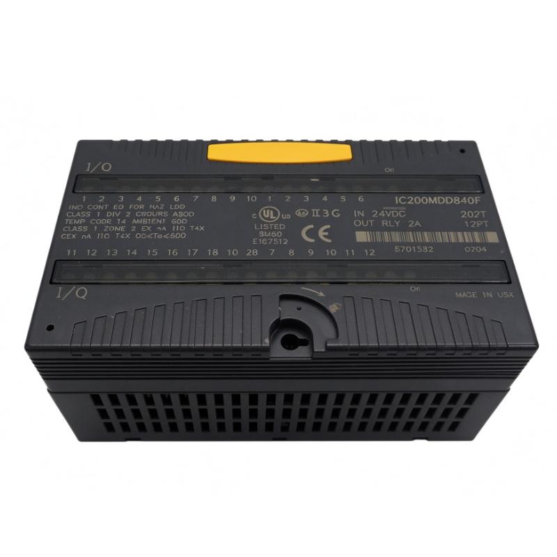
1. Product Overview
The GE IC200MDD840 is a VersaMax Discrete Mixed I/O Module designed for industrial automation and PLC control applications. It combines 20 discrete inputs with 12 relay outputs in a single module, allowing a controller to monitor field signals and operate external devices through one compact I/O unit.
The input section accepts 24 VDC positive-logic signals from field devices such as proximity sensors, pushbuttons, limit switches, and other discrete control equipment. The output section uses relay contacts to switch external AC or DC loads, making the module suitable for applications that require flexible load control.
The IC200MDD840 is commonly used in machine automation, manufacturing equipment, process control panels, and distributed control systems. Its mixed input/output design helps reduce the number of separate I/O modules required in a control cabinet.
2. Technical Specifications
| Parameter | Specification |
|---|---|
| Manufacturer | GE Fanuc / GE Intelligent Platforms |
| Model | IC200MDD840 |
| Product family | VersaMax |
| Module type | Discrete Mixed I/O Module |
| Input configuration | 20-point, 24 VDC positive logic |
| Input grouping | 2 groups of 10 points |
| Output configuration | 12-point relay output |
| Output grouping | 2 groups of 6 points |
| Relay output rating | 2.0 A per point within the specified load limits |
| Maximum output group current | 8 A per group |
| Nominal input voltage | 24 VDC |
| Relay output voltage range | 5–265 VAC or 5–125 VDC, subject to load-dependent current limits |
| Backplane power | Supplied through the VersaMax carrier |
| Output load power | Requires an external power source |
| Input response | Basic response approximately 0.5 ms; configurable filtering available |
| Module dimensions | Approx. 110 × 66.8 × 50 mm, excluding carrier and mating connections |
Important: The relay output current depends on the applied voltage, load type, switching conditions, and group-current limits. The 2 A per-point rating must not be interpreted as permission to draw 2 A from all 12 points simultaneously. Verify the complete load table and derating requirements in the applicable module documentation before wiring.
3. Main Functions and Operating Principle
3.1 Twenty 24 VDC Positive-Logic Inputs
The IC200MDD840 provides 20 discrete input points arranged in two groups of 10. The inputs are designed for 24 VDC positive-logic signals. They receive current from connected field devices and return it through the corresponding common connection.
Typical input devices include:
- Proximity and photoelectric sensors.
- Pushbuttons and selector switches.
- Limit switches and position contacts.
- Machine status contacts.
- Discrete alarm and interlock signals.
The input circuitry converts the electrical state of each field signal into discrete input data for the PLC controller. The CPU or network interface unit performs the application-level processing.
3.2 Twelve Relay Outputs
The output section provides 12 relay output points divided into two groups of six. Each output uses a relay contact to switch an external load. This allows the module to control compatible AC or DC devices without requiring the load voltage to be the same as the 24 VDC input voltage.
Typical applications include operating interposing relays, contactor coils, indicator lamps, and other compatible control loads. The output loads require an external power source; the module’s backplane supply does not directly provide the field load power.
3.3 Grouped Output Arrangement
The 12 relay outputs are organized into two groups of six. Each group has a maximum current capacity that must be observed when several loads operate simultaneously.
When planning the wiring, consider both the current of each individual relay point and the combined current of its output group. Also check the voltage and load-type restrictions for AC and DC switching.
3.4 LED Status Indication
The module provides individual green LED indicators for input and output points, along with an OK status indicator.
- Input LEDs: Indicate the logical on/off state of the corresponding input points.
- Output LEDs: Indicate the commanded logical state of the output points. They are logic-driven and do not independently prove that the external load is energized.
- OK LED: Indicates that backplane power is present at the module.
When diagnosing a fault, compare the LED indication with PLC logic, field-device status, and actual electrical measurements. An illuminated output LED does not guarantee that a relay contact or connected load is functioning correctly.
4. Installation Preparation
4.1 Verify the Carrier and System Compatibility
The IC200MDD840 must be installed with a compatible VersaMax carrier and the appropriate field wiring arrangement. Do not assume that every VersaMax terminal base or interposing terminal assembly supports this module.
The IC200MDD840 has a non-symmetrical distribution of inputs and outputs. Its terminal arrangement must therefore be checked carefully against the carrier and wiring documentation. In particular, do not assume that the IC200CHS101 disconnect-style main base is suitable simply because it belongs to the VersaMax family.
Before installation, verify:
- Exact module part number: IC200MDD840.
- Compatible VersaMax carrier model.
- Correct field terminal arrangement.
- Input group and common connections.
- Relay output group connections.
- External load power requirements.
- Available backplane power capacity.
4.2 Prepare Tools and Materials
- Appropriate insulated screwdrivers and hand tools.
- Wire stripping and termination tools.
- Approved electrical measuring instruments.
- Field wiring labels and identification markers.
- Suitable 24 VDC input supply.
- External power supplies for relay output loads.
- Compatible VersaMax carrier and terminal assembly.
- Current wiring diagrams and module documentation.
- ESD protection equipment.
4.3 Review Electrical and Load Requirements
Calculate the expected current for every relay output and the combined current for each six-point output group. Confirm that the connected load is within the permitted voltage and current ratings.
Pay particular attention to inductive loads such as relay and contactor coils. Switching inductive loads can produce transient voltages that may shorten relay contact life. Use suitable external suppression where required by the load and system design. The IC200MDD840 should not be assumed to include internal fuses or built-in output snubbers.
5. Installation Procedure
Step 1: Isolate the Equipment
Before installing the module, shut down the relevant equipment according to the plant’s approved procedure. Isolate the PLC system and all external field power sources that may energize the input or output wiring.
Apply lockout/tagout where required and verify that the work area is electrically safe. Remember that relay output circuits may use external AC or DC supplies even when the PLC backplane is switched off.
Step 2: Inspect the Module
Check the IC200MDD840 for physical damage, contamination, bent contacts, cracked housing, or signs of overheating. Confirm that the product label matches the intended module and that the connector area is clean and undamaged.
Do not install a module that shows signs of severe electrical or mechanical damage.
Step 3: Prepare the VersaMax Carrier
Install the compatible VersaMax carrier in the designated control cabinet location. Confirm that the carrier is securely mounted and correctly aligned with the system backplane and field wiring arrangement.
Verify that the carrier model supports the IC200MDD840. Because this module has a non-symmetrical input/output distribution, the correct terminal arrangement is particularly important.
Step 4: Mount the I/O Module
Align the IC200MDD840 with the carrier connector and mounting features. Carefully engage the module without applying excessive force. Confirm that the module is fully seated and mechanically secured according to the carrier installation procedure.
Inspect the mating connection to ensure that there is no visible misalignment or obstruction.
Step 5: Connect the 24 VDC Input Circuits
Connect the 20 positive-logic input circuits according to the module-specific wiring diagram. The inputs are divided into two groups of 10 points, so the correct common and return arrangements must be observed.
For each input circuit:
- Identify the field device and corresponding PLC input address.
- Verify the 24 VDC supply polarity and common arrangement.
- Confirm the terminal assignment against the module wiring diagram.
- Use suitable conductors and approved termination methods.
- Label the field wiring clearly.
- Check that no loose strands or exposed conductors can cause short circuits.
Do not use an assumed terminal pinout. The actual carrier and module wiring diagram must determine each terminal connection.
Step 6: Connect the Relay Output Circuits
Connect the 12 relay output circuits to their corresponding field loads. The outputs are arranged in two groups of six. Use an external load supply appropriate for the connected devices and the relay contact ratings.
During wiring:
- Identify the output point and its assigned PLC address.
- Confirm the relay contact arrangement from the module documentation.
- Check the voltage and current requirements of the load.
- Calculate the total current for each six-point output group.
- Use suitable protective devices in the external load circuits.
- Provide appropriate suppression for inductive loads where required.
- Keep AC and DC wiring appropriately separated according to cabinet design and applicable standards.
Step 7: Check the Output Group Current
Each relay output point has an individual current limit, and each six-point group has a maximum combined current limit. Verify both values when designing the load arrangement.
For example, a design with several relay outputs operating simultaneously must be evaluated using the total group current, not just the individual point ratings. Ensure that expected operating conditions, including simultaneous switching and load inrush, remain within the specified limits.
Step 8: Inspect and Secure All Wiring
After completing the wiring, compare every connection with the approved drawings. Check terminal tightness using the specified torque where applicable. Confirm that field conductors are identified and routed without excessive mechanical stress.
Verify that no unused conductor ends, loose metal strands, or tools remain inside the cabinet.
6. Configuration and Commissioning
6.1 Input Filter Configuration
The IC200MDD840 has a basic input on/off response time of approximately 0.5 ms. Additional filtering can be selected through software configuration to help reduce the effects of electrical noise or mechanical switch bounce.
Common selectable filter settings include 0 ms, 1.0 ms, and 7.0 ms. Including the basic response, the corresponding total response times are approximately 0.5 ms, 1.5 ms, and 7.5 ms.
Choose a filter setting that matches the application. A longer filter can help reject short disturbances, but it also increases the time required for an input transition to be recognized. Applications involving rapid events should be evaluated carefully before increasing the filter time.
6.2 Check Backplane Power
Restore the PLC backplane supply according to the system startup procedure. Check the module’s OK LED and the controller’s hardware diagnostics.
The OK LED should indicate that backplane power is present. If it remains off, investigate the carrier, rack power supply, module seating, and backplane connections before assuming that the I/O module has failed.
6.3 Verify Input Operation
Operate each field input device under controlled conditions and observe the corresponding input LED and PLC input data.
Confirm that:
- The field device changes state correctly.
- The corresponding input LED responds.
- The PLC input address reflects the expected state.
- The selected input filter provides acceptable response time.
- Unrelated input points remain stable.
6.4 Verify Relay Output Operation
Use the PLC programming environment or approved control procedure to command each relay output. Check the corresponding output LED and verify the relay contact state using an appropriate electrical test method.
Confirm that the connected load operates correctly and that the external supply remains within its specified range. Do not rely on the output LED alone as evidence of a functioning relay contact.
6.5 Perform a Controlled Load Test
Test the output circuits under representative operating conditions. Where several outputs operate together, verify that the combined current for each group remains within the documented limit.
Observe relay switching behavior, load response, and any abnormal heating or electrical noise. Stop testing if an unexpected condition appears.
7. System Integration and Application Considerations
The IC200MDD840 combines field signal acquisition and relay-based load control in one VersaMax module. The CPU or network interface unit handles the processing of input and output data, while the module provides the physical interface to the field circuits.
Typical applications include:
- Automated production machinery.
- Packaging and material handling systems.
- Machine status monitoring and interlocking.
- Industrial equipment sequencing.
- Control of compatible relay-switched AC and DC loads.
- PLC systems requiring both discrete input monitoring and relay output control.
When integrating the module, confirm the controller configuration, input addressing, output addressing, filter settings, carrier compatibility, and external load power arrangement. The module does not replace the need for correctly rated external circuit protection.
8. Maintenance Recommendations
- Inspect the module and carrier for secure mechanical mounting.
- Check field terminals for looseness, corrosion, and overheating.
- Review recurring input and output diagnostic faults.
- Check relay output loads against their specified current limits.
- Inspect external suppression components used with inductive loads.
- Verify that cabinet temperature and ventilation remain within equipment requirements.
- Keep wiring drawings and PLC configuration records up to date.
- Maintain suitable spare modules where required by operational availability targets.
Relay contacts are electromechanical components and can wear over time, particularly when switching high-current or inductive loads. If a relay output becomes unreliable, evaluate the load conditions and switching history before deciding whether the module should be replaced.
9. Frequently Asked Questions
How many inputs and outputs does the IC200MDD840 provide?
The IC200MDD840 provides 20 discrete 24 VDC positive-logic inputs and 12 relay outputs.
How are the input points arranged?
The 20 inputs are divided into two groups of 10 points.
How are the relay outputs arranged?
The 12 relay outputs are divided into two groups of six points. Each point and each group must remain within its specified current limits.
Does the module require an external power supply?
The module receives its operating power from the VersaMax backplane. However, the relay output loads require an external power source.
Can the relay outputs switch AC and DC loads?
Yes. The relay contacts support specified AC and DC load applications. The permitted voltage and current depend on the load type and the module’s rating table.
Does the IC200MDD840 have built-in output fuses?
The module should not be assumed to provide internal output fuses or snubbers. Appropriate external protection and load suppression must be considered in the system design.
What does the OK LED indicate?
The OK LED indicates the presence of backplane power at the module. It does not independently verify that all input circuits and relay contacts are functioning correctly.
Can the IC200MDD840 be installed on any VersaMax terminal base?
No. The carrier and field terminal arrangement must be compatible with the module’s non-symmetrical input/output distribution. Verify the exact hardware combination before installation.
10. Conclusion
The GE IC200MDD840 VersaMax Discrete Mixed I/O Module combines 20 positive-logic 24 VDC inputs and 12 relay outputs in one compact PLC module. Its grouped input and relay output architecture supports a range of industrial control applications where field signal monitoring and relay-based load switching are required.
Successful installation depends on selecting the correct VersaMax carrier, following the module-specific terminal arrangement, providing suitable external power for relay loads, and respecting both individual output and group-current limits. Careful commissioning of input filtering, LED indications, PLC data, and relay contact operation helps establish reliable system performance.
Technical Summary
The GE IC200MDD840 is a VersaMax Discrete Mixed I/O Module with 20 24 VDC positive-logic inputs arranged in two groups of 10 and 12 relay outputs arranged in two groups of six. Each relay output is rated up to 2.0 A within the specified load conditions, with a maximum group current of 8 A. The module receives operating power from the VersaMax backplane, while relay output loads require external power. Correct carrier compatibility, terminal wiring, input filter configuration, and output load calculations are essential for reliable installation and commissioning.