
NewsNEWCENTER
Featured products
Contact Us
GE IC200CHS101 Disconnect-Style Interposing I/O Terminal Main Base Troubleshooting Guide
2026-11-10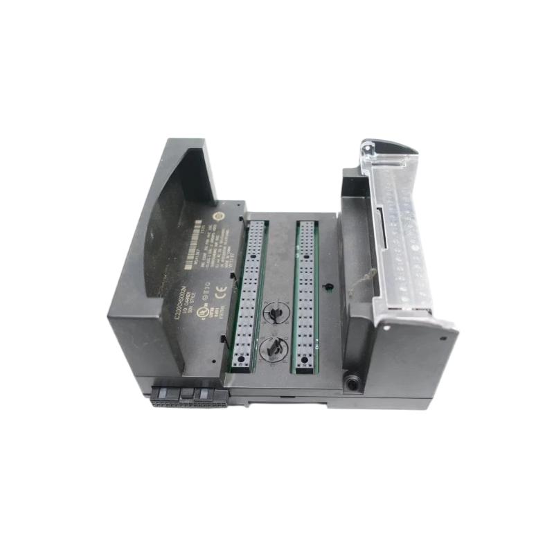
1. Introduction
The GE IC200CHS101 is a Disconnect-Style Interposing I/O Terminal Main Base designed for the GE Fanuc VersaMax PLC platform. It provides a field wiring interface between a compatible connector-style I/O carrier and external industrial devices. Its integrated knife-switch disconnects allow individual signal or return circuits to be isolated for testing and maintenance.
When an IC200CHS101 installation develops a fault, the symptoms may include missing input signals, inactive outputs, intermittent I/O operation, or unexpected PLC diagnostic indications. These problems do not necessarily mean that the terminal base itself has failed. Incorrect wiring, open disconnect switches, carrier cable problems, incompatible I/O modules, and field-device faults should also be considered.
This guide explains how to inspect the terminal base, identify common problems, troubleshoot field circuits, and determine when replacement is appropriate.
2. Product Identification and Main Components
| Parameter | Description |
|---|---|
| Manufacturer | GE Fanuc / GE |
| Model | IC200CHS101 |
| Product type | Disconnect-Style Interposing I/O Terminal |
| Base configuration | Main Base |
| PLC platform | VersaMax |
| Carrier connector | J1 |
| Expansion connector | J2 |
| Field wiring terminals | 36 box-style terminals |
| Main I/O terminal group | A1–A18 |
| Auxiliary terminal groups | W1–W8 and X1–X8 |
| Disconnect mechanism | Individual knife-switch disconnects |
| Related expansion base | IC200CHS102 |
| Approximate dimensions | 115 × 126 × 65 mm |
The IC200CHS101 is a passive interposing terminal assembly rather than an independent PLC I/O processing module. Its condition must therefore be evaluated together with the connected I/O carrier, module, field wiring, and external devices.
3. Common Fault Symptoms
3.1 One Input Signal Is Missing
A missing input signal may occur when a field device is disconnected from the control circuit, a conductor is loose, or the associated signal path is interrupted.
Possible causes include:
- The relevant knife-switch disconnect is open.
- A field conductor is loose or incorrectly terminated.
- The field device has no power or is malfunctioning.
- The carrier cable or connector has poor contact.
- The associated I/O module has a channel fault.
- The terminal assignment does not match the module wiring diagram.
Start by checking the field device and the corresponding terminal path. Confirm the switch position before investigating the PLC module itself.
3.2 One Output Does Not Operate
If a PLC output command is present but the field device does not respond, the fault may be located in the output circuit rather than the terminal base.
Check the output module status, field supply, wiring polarity where applicable, disconnect-switch position, and connected load. Also verify whether the output module’s electrical characteristics are suitable for the field device.
3.3 Multiple I/O Channels Fail at the Same Time
When several channels become unavailable simultaneously, investigate shared connections and common circuits before assuming that multiple individual terminal positions have failed.
Potential causes include:
- A loose or incorrectly connected J1 carrier cable.
- A problem affecting a shared field supply or common connection.
- Incorrect auxiliary terminal jumpers.
- An I/O module or carrier fault.
- Incorrect terminal-base compatibility or wiring configuration.
3.4 Intermittent Signal Operation
Intermittent I/O behavior may be associated with loose conductors, poor connector contact, vibration, contamination, or a damaged disconnect mechanism.
Review the timing of the fault and determine whether it occurs during machine movement, temperature changes, cabinet vibration, or other operating conditions. Inspect the terminal assembly only after following the required electrical isolation procedure.
3.5 Problems After Maintenance or Replacement
If an I/O problem appears immediately after terminal-base replacement, module replacement, or cabinet maintenance, check for installation-related errors.
Typical issues include incorrect connector orientation, a misplaced cable, changed terminal assignments, missing auxiliary jumpers, or an incompatible I/O module. Compare the current arrangement with the original wiring drawings and maintenance records.
4. Safety Precautions Before Troubleshooting
Although the IC200CHS101 is an interposing terminal base, its field terminals may be connected to energized industrial circuits. Follow the site’s electrical safety procedures before inspection or testing.
- Apply lockout/tagout where required before handling wiring or connectors.
- Identify and isolate external field power supplies as well as PLC-related power sources.
- Verify the electrical condition of the circuit with suitable test equipment.
- Do not assume that opening a knife switch makes every connected conductor safe.
- Use appropriate insulated tools and personal protective equipment.
- Follow ESD precautions when handling the associated electronic carrier or I/O module.
- Do not disconnect process-critical signals without authorization and an approved operating plan.
5. Step-by-Step Troubleshooting Procedure
Step 1: Identify the Affected I/O Channel
Begin by determining exactly which input or output is affected. Record the PLC address, I/O module model, field-device tag, terminal number, and fault description.
Compare the PLC diagnostic information with the actual field-device condition. This helps establish whether the problem is related to the field circuit, terminal base, carrier connection, or I/O module.
Step 2: Check the Field Device and External Supply
Before inspecting the terminal base, verify that the field device is operating and receiving the required supply. Check the external wiring and any relevant field protection devices.
For an input circuit, confirm that the field device produces the expected signal. For an output circuit, verify that the field load and its supply are suitable for the connected output module.
Use the electrical specifications and wiring diagram for the actual module. Do not apply assumed voltage or current values.
Step 3: Inspect the Knife-Switch Disconnects
The IC200CHS101 includes individual disconnect switches for supported signal and common paths. An open switch can interrupt the corresponding field circuit.
Check the switch associated with the affected channel and confirm that it is in the intended operating position. Inspect for mechanical damage, obstruction, or signs of overheating.
Do not move a disconnect switch while a circuit is operating unless the process procedure and equipment documentation explicitly permit it. Some connected devices may be affected immediately when a signal or return path is opened.
Step 4: Inspect Field Wiring Terminations
Check the conductor connected to the affected terminal. Look for loose wires, damaged insulation, corrosion, broken conductors, and poor termination.
- Confirm the terminal designation against the module-specific wiring diagram.
- Check that the conductor is correctly prepared and secured.
- Look for loose strands or exposed copper.
- Check for signs of overheating or discoloration.
- Verify that field labels match the actual wiring.
Where a terminal connection requires adjustment, isolate the circuit and use the specified termination procedure and torque value. Do not guess the tightening torque.
Step 5: Check the J1 Carrier Connection
The J1 connector connects the IC200CHS101 to the cable from the VersaMax connector-style I/O carrier. A damaged, loose, or incorrectly seated cable can affect one or multiple I/O signals.
Inspect the connector housing, contacts, cable condition, and mechanical retention. Confirm that the cable is the correct type and is connected in the intended orientation.
If reconnection is required, follow the approved isolation procedure first. Avoid unnecessary connector cycling because repeated handling can damage contacts.
Step 6: Check the J2 Expansion Connection
The J2 connector is used to connect the IC200CHS101 to a compatible IC200CHS102 expansion base when B-side connections are required.
If B-side signals are affected, inspect the expansion cable and both connector interfaces. Check for loose connections, cable damage, or incorrect installation.
If the system does not require an expansion base, do not assume that an unused J2 connection is a fault. Evaluate the installed configuration against the actual I/O module requirements.
Step 7: Verify Auxiliary Common Connections
The IC200CHS101 provides two groups of auxiliary terminals, W1–W8 and X1–X8, for supported two-wire field-device connections. Each group has a dedicated connection point for the corresponding auxiliary terminal group.
Incorrect or missing jumper arrangements can cause unexpected signal behavior, particularly when the I/O module uses grouped return connections.
Check the module-specific wiring diagram to confirm whether the W and X groups require jumpers and how they should be connected. Do not install or move jumpers based on assumptions or another module’s wiring arrangement.
Step 8: Verify I/O Module Compatibility
Not every VersaMax I/O module is compatible with every interposing terminal arrangement. Some modules use A-side connections only, while others require both A-side and B-side connections. Certain modules may have special terminal distribution requirements.
Confirm the module model against the applicable VersaMax compatibility information. If the module requires B-side connections, verify that the IC200CHS102 expansion base is installed and wired correctly.
Step 9: Perform Electrical Continuity and Signal Tests
When visual inspection does not identify the problem, qualified personnel can perform appropriate continuity and signal-path tests using the approved procedure.
Before testing, isolate the relevant circuit and disconnect equipment as required to avoid damaging connected electronics or creating misleading measurements.
Compare test results with the wiring diagram and the electrical specifications of the connected module and field device. Do not assume that a continuity result alone confirms correct operation under load.
Step 10: Determine Whether the Terminal Base Is Defective
Consider replacing the IC200CHS101 when there is clear evidence of physical damage, a defective disconnect mechanism, damaged connector contacts, or an internal connection fault that cannot be corrected through approved maintenance.
If the terminal base passes inspection and continuity checks, continue investigating the I/O module, carrier, field supply, field device, and PLC configuration.
6. Troubleshooting Reference Table
| Symptom | Possible Cause | Recommended Action |
|---|---|---|
| Single input missing | Open disconnect switch, loose wiring, or field-device fault | Check the affected signal path and field device |
| Single output inactive | Open circuit, missing field supply, or output-module fault | Verify the load, supply, wiring, and module status |
| Several channels unavailable | J1 connection issue, common circuit fault, or module problem | Inspect shared connections and common wiring |
| Intermittent signals | Loose conductors, vibration, contamination, or damaged switch | Inspect terminals and disconnect mechanisms |
| B-side signals unavailable | Missing or incorrectly connected IC200CHS102 expansion base | Inspect J2 and the expansion cable |
| Unexpected two-wire device behavior | Incorrect W/X auxiliary terminal jumper arrangement | Verify the module-specific wiring diagram |
| Fault after replacement | Incorrect wiring, connector placement, or module incompatibility | Recheck part numbers, connections, and configuration |
7. Understanding the IC200CHS101 and IC200CHS102
The IC200CHS101 is the main base and provides the A-side terminal connections A1–A18. The IC200CHS102 is the expansion base and provides the B-side terminal connections B1–B18.
Both bases provide individual disconnect functionality and auxiliary common terminal groups. The main base uses W1–W8 and X1–X8, while the expansion base uses Y1–Y8 and Z1–Z8.
When troubleshooting, distinguish between an A-side problem and a B-side problem. If only the B-side signals are affected, the expansion base and its ribbon cable deserve particular attention. If both sides are affected, investigate shared connections, the I/O carrier, the module, and common field supplies.
8. Repair and Replacement Guidelines
8.1 When Repair May Be Appropriate
Some problems can be corrected without replacing the complete terminal base. Examples include a loose field conductor, an incorrectly positioned disconnect switch, a damaged external cable, or an incorrect auxiliary jumper arrangement.
Any repair must follow the approved maintenance procedure. Do not modify internal connections or attempt improvised repairs to damaged switching mechanisms.
8.2 When Replacement Is Recommended
Replacement should be considered when the terminal base has cracked housing, damaged connector contacts, persistent internal connection problems, or a mechanically defective disconnect switch.
Before installing a replacement, verify:
- The exact part number IC200CHS101.
- Compatibility with the installed VersaMax I/O module.
- Correct J1 carrier cable connection.
- Correct J2 expansion arrangement, if applicable.
- Field terminal assignments and auxiliary jumper configuration.
- Mechanical mounting and cabinet clearance.
8.3 Post-Replacement Testing
After replacement, compare all wiring with the original drawings and verify each disconnect switch position. Restore power according to the plant’s approved startup procedure.
Check the PLC diagnostics and test the affected field signals. Where possible, verify both the affected channel and the surrounding channels to confirm that the replacement has not introduced additional wiring problems.
9. Preventive Maintenance
- Inspect field wiring and terminal condition during scheduled maintenance.
- Check the mechanical condition of each disconnect switch.
- Inspect J1 and J2 connectors for damage and poor seating.
- Keep the terminal assembly clean and free from conductive contamination.
- Check mounting security in installations subject to vibration.
- Maintain accurate terminal labels and wiring drawings.
- Record changes to auxiliary jumpers and expansion-base connections.
- Keep compatible replacement terminal bases available where operational requirements justify spare inventory.
10. Frequently Asked Questions
What is the main function of the IC200CHS101?
It provides a field wiring interface for compatible VersaMax connector-style I/O carriers and allows individual signal or return circuits to be disconnected through integrated knife switches.
Why is one input signal missing?
Possible causes include an open disconnect switch, loose wiring, a defective field device, an incorrect terminal assignment, a carrier cable problem, or an I/O module fault.
What is the purpose of the J1 connector?
J1 connects the main terminal base to the cable from the VersaMax connector-style I/O carrier.
What is the purpose of the J2 connector?
J2 provides the expansion connection for a compatible IC200CHS102 base when B-side terminal connections are required.
Can the IC200CHS101 work without an IC200CHS102?
Yes, when the selected I/O module and application require only the A-side connections. An expansion base is needed when the module requires B-side field connections.
Can an open disconnect switch cause an I/O fault?
Yes. Opening the switch associated with a signal or return path can interrupt the corresponding field circuit and cause the connected input or output to behave differently.
Does the IC200CHS101 have its own diagnostic LED?
It is an interposing terminal base rather than an active I/O processing module. Troubleshooting should focus on its wiring, disconnect mechanisms, connectors, and the diagnostic information provided by the associated VersaMax I/O module and PLC.
11. Conclusion
The GE IC200CHS101 Disconnect-Style Interposing I/O Terminal Main Base is an important field wiring interface in compatible VersaMax PLC installations. Its individual knife-switch disconnects make it possible to isolate selected field circuits for maintenance while retaining the existing wiring arrangement.
Effective troubleshooting requires checking the complete signal path, including the field device, terminal connections, disconnect switches, auxiliary common wiring, J1 carrier connection, and any J2 expansion connection. Confirming I/O module compatibility and following the correct wiring diagram are essential to avoiding unnecessary replacement and recurring faults.
Technical Summary
The GE IC200CHS101 is a VersaMax Disconnect-Style Interposing I/O Terminal Main Base with 36 box-style terminals, J1 carrier connection, J2 expansion connection, A1–A18 signal terminals, W1–W8 and X1–X8 auxiliary terminals, and individual knife-switch disconnects. Common troubleshooting areas include open disconnect switches, loose field wiring, carrier cable problems, incorrect auxiliary jumper arrangements, and incompatible I/O configurations. The IC200CHS102 expansion base is used when B-side connections are required.