

ProductPRODUCT
Featured products
Contact Us
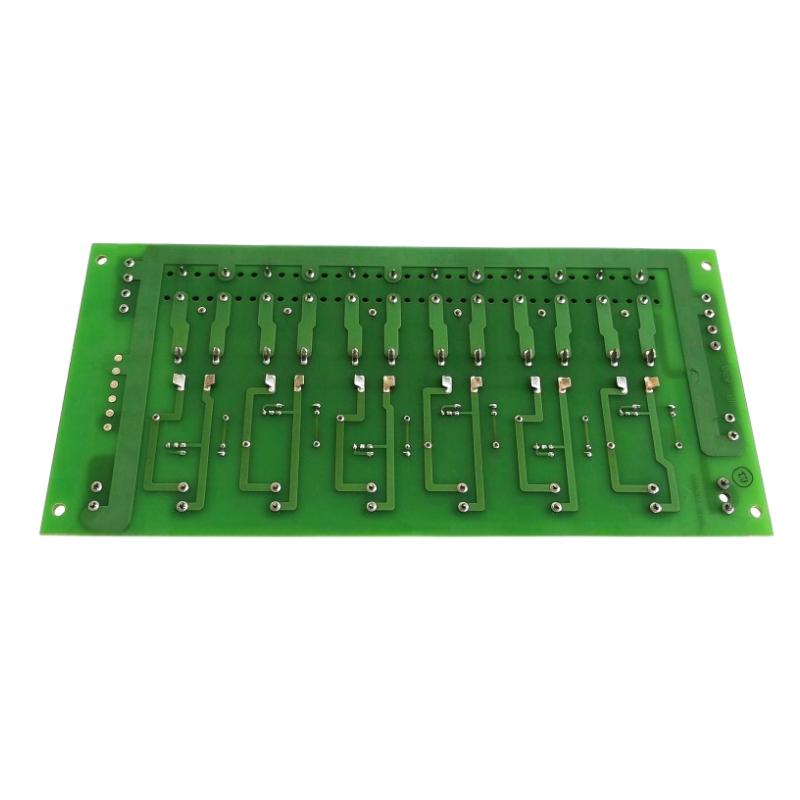
- GE
- IS210JPDDG3A
- DC Switchboard
- USA
- 234 × 30 × 108 mm
- 0.55 kg
- Xiamen, China
- New & In Stock
- T/T, PayPal, Western Union
- 1 Year
- 1-3 Working Days
- DHL, UPS, TNT, FedEx and EMS.
- 24-Hour Service
- COO
- 4
Our advantage

Global Logistics
We have a 10-year logistics and express cooperation agreement, so our products can be shipped to any place in the world.

Brand new and original
Our products are imported in bulk from the place of origin. Because of the cooperative relationship, our products are all original and 100% new.

24-hour service
We provide 7*24 hours service to our customers. We will be there whenever you need us.

Price advantage
All our products are priced very favorably because we have our own warehouse and supply.
| Company Information | |||
| [email protected] | |||
| Mobile | +8615980777398 | ||
| +8615980777398 | |||
| 15980777398 |
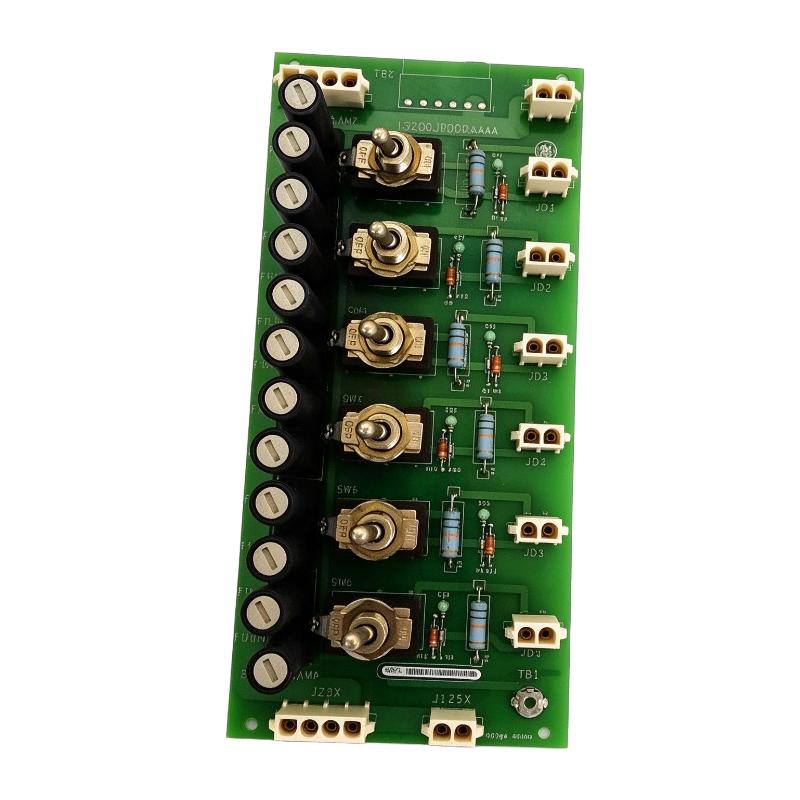
Product Overview
The GE IS210JPDDG3A DC Power Distribution Module is an industrial power distribution component designed for GE Mark VIe turbine control systems. It provides organized distribution, isolation, and branch-circuit protection for DC-powered control and auxiliary circuits.
In industrial turbine control systems, reliable DC power distribution is essential for maintaining the operation of control devices, relay circuits, solenoid valves, and other electrical equipment. The IS210JPDDG3A helps organize these power connections and provides individual branch protection to support maintenance and troubleshooting.
The module belongs to the GE Mark VIe DC Power Distribution (JPDD) family. It is designed to work with compatible DC power sources and can support nominal input levels of 24 V DC, 48 V DC, or 125 V DC. Only one voltage level should be applied at a time.
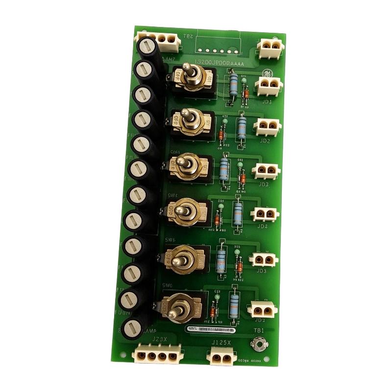
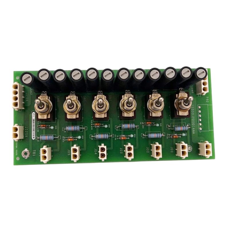
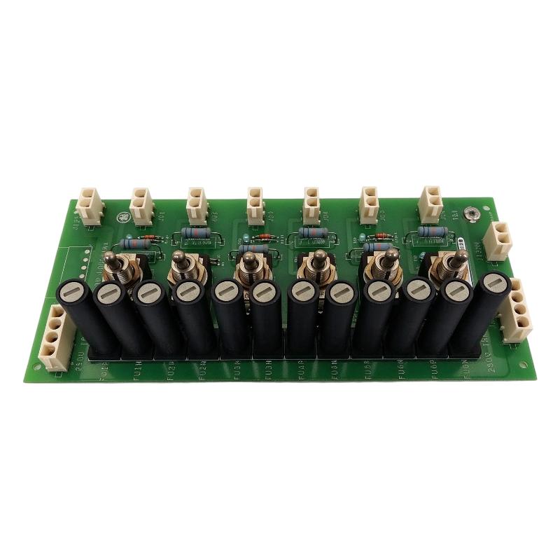
Each output branch incorporates a fuse, a switch, and an indicator lamp. These features allow maintenance personnel to isolate individual circuits and identify whether output voltage is present. The module is particularly relevant to applications involving DC relay control power, solenoid valve circuits, and contact-wetting circuits.
The IS210JPDDG3A is designed for DIN-rail mounting and is associated with GE Mark VIe control installations. It should be selected according to the required input voltage, branch fuse ratings, wiring arrangement, and system configuration.
It is important to distinguish this component from a DC-DC converter. The IS210JPDDG3A distributes and protects DC power; it does not independently convert a 125 V DC input into a regulated 24 V DC output.
Technical Specifications
| Parameter | Specification |
|---|---|
| Brand | GE |
| Manufacturer | General Electric |
| Model | IS210JPDDG3A |
| Product Type | DC Power Distribution Module |
| Common Description | DC Switchboard / DC PDM |
| Product Series | Mark VIe |
| Functional Group | JPDD DC Power Distribution |
| Input Voltage Options | 24 V DC, 48 V DC, or 125 V DC |
| Input Configuration | One voltage level at a time |
| Distribution Function | DC power distribution and isolation |
| Branch Protection | Fused outputs |
| Output Control | Individual branch switches |
| Status Indication | Indicator lamp for output voltage presence |
| Mounting | Vertical DIN rail |
| Typical Applications | DC relay control power, solenoid valve circuits, contact wetting |
| Dimensions Provided | 234 × 30 × 108 mm |
| Weight Provided | 0.55 kg |
| System Application | GE Mark VIe turbine control systems |
Note: Dimensions and weight are supplied listing values. Confirm the exact assembly and mounting arrangement before finalizing panel layout or shipping information. Actual branch fuse ratings must be checked against the installed module and system documentation.
Function and Working Principle
The IS210JPDDG3A is designed to distribute DC power from a compatible source to multiple downstream control circuits. Its main functions include power distribution, circuit isolation, branch protection, and local output-status indication.
1. DC Power Distribution
The module receives DC power through its designated input connections and distributes it to the required downstream circuits.
Depending on the system design, the input may be 24 V DC, 48 V DC, or 125 V DC. These are alternative operating voltage levels, not simultaneous inputs.
A centralized distribution arrangement helps organize electrical connections within a turbine control cabinet. It can also make it easier for engineers to identify individual power branches during installation and maintenance.
2. Individual Branch Protection
Each output branch incorporates a fuse to provide overcurrent protection for its associated circuit.
If a downstream circuit develops a fault that causes excessive current, the appropriate fuse can interrupt the affected branch. This helps limit the impact of an electrical fault on the wider distribution arrangement.
Fuse selection is important. The rating must be coordinated with the connected load, wiring, connectors, and applicable system requirements. The correct fuse type and rating should always be verified against the GE documentation for the specific configuration.
3. Output Isolation
Individual branch switches allow maintenance personnel to isolate selected DC circuits.
This function is useful when troubleshooting a relay, solenoid valve, or auxiliary control circuit. Instead of disconnecting the entire distribution arrangement, authorized personnel can isolate the relevant branch according to the approved maintenance procedure.
Branch switches should not be treated as substitutes for all required electrical isolation and lockout procedures.
4. Output Voltage Indication
Each output includes an indicator lamp that provides a visual indication of output voltage presence.
This feature can help technicians identify whether a branch is energized during inspection and troubleshooting. However, an indicator lamp is not a substitute for electrical measurement. Personnel should use appropriate test equipment and verify safe conditions before handling conductors.
5. DC Power Connection and Expansion
The JPDD design provides input and distribution connections that can support the arrangement of multiple compatible distribution modules.
Depending on the selected voltage input and wiring configuration, the module uses designated connectors for DC power distribution. The manufacturer’s documentation describes connector arrangements for 125 V DC and for 24/48 V DC applications.
Where multiple modules are connected, engineers must verify connector assignments, polarity, current capacity, grounding, and the permitted distribution arrangement.
Role in GE Mark VIe Control Systems
The IS210JPDDG3A supports the electrical power architecture of GE Mark VIe turbine control systems. It is used to distribute DC power to compatible control and auxiliary circuits.
1. Supporting Turbine Control Circuits
Turbine control systems rely on numerous electrical devices to monitor operating conditions and execute control commands.
The JPDD module can provide organized DC power distribution for selected control circuits, including relay and solenoid-related applications. Reliable power distribution helps maintain the electrical connections required by the wider control system.
2. Relay and Solenoid Valve Power
Industrial turbine systems use relays and solenoid valves in control and auxiliary functions.
The IS210JPDDG3A is suitable for distributing DC control power to compatible relay and solenoid circuits. Individual branch protection and isolation can help maintenance personnel identify and address problems in these circuits.
The module’s actual output voltage must match the connected devices. It should not be assumed that every output is 24 V DC regardless of the selected input voltage.
3. Contact-Wetting Applications
Contact-wetting circuits use an appropriate electrical signal or voltage to support reliable monitoring of electrical contacts.
The JPDD family is used in applications that require DC contact-wetting power. The required voltage and circuit arrangement must be confirmed against the specific system design.
4. Cabinet-Level Power Organization
The module provides a centralized arrangement for DC power connections, branch switches, fuses, and status indicators.
This can help simplify cabinet wiring and make the distribution system easier to inspect. It also supports a more structured maintenance process by allowing individual branches to be checked and isolated.
5. Supporting System Availability
In turbine control environments, electrical faults can affect important auxiliary and control functions.
Branch-level protection helps limit the electrical impact of certain downstream faults. However, the module does not guarantee uninterrupted power or replace redundant power supplies, system-level protection, or other reliability measures.
Industrial Applications
The GE IS210JPDDG3A is primarily associated with turbine control and industrial DC power distribution applications.
1. Gas Turbine Control Systems
Gas turbine installations use DC-powered control circuits for a variety of auxiliary and operating functions.
The IS210JPDDG3A can provide branch-level power distribution for compatible relay and solenoid control circuits within a properly configured GE Mark VIe installation.
2. Steam Turbine Control Systems
Steam turbine control installations also require organized electrical distribution for auxiliary control devices and associated circuits.
Where the module is included in a compatible system design, it can support the distribution and isolation of selected DC-powered control branches.
3. Industrial Relay Circuits
Industrial relay systems use DC control power to operate switching devices and interface circuits.
The module’s fused outputs and branch switches provide a convenient arrangement for distributing and isolating power to compatible relay circuits.
4. Solenoid Valve Control
Solenoid valves are widely used in industrial equipment to control pneumatic, hydraulic, and process-fluid functions.
The IS210JPDDG3A can distribute DC control power to compatible solenoid circuits when the selected input voltage and branch configuration match the connected devices.
5. Turbine Control Cabinets
The DIN-rail mounting arrangement makes the module suitable for installation in appropriately designed electrical control cabinets.
Its branch-level switches, fuses, and indicator lamps help organize the DC distribution system and support routine inspection.
Installation and System Integration
Correct installation is essential for electrical safety and reliable operation.
1. Verify the Input Voltage
Before installation, identify the required DC voltage level for the application.
The JPDD design supports 24 V DC, 48 V DC, or 125 V DC configurations. Only one voltage level should be applied at a time.
Do not connect multiple voltage levels simultaneously. Confirm the installed configuration and connector assignments using the applicable GE documentation.
2. DIN-Rail Mounting
The module is installed in a plastic mounting holder designed for a vertical DIN rail.
Ensure that the mounting rail is secure and that the module is properly retained. Allow sufficient space for wiring access, fuse inspection, switch operation, and maintenance.
The supplied dimensions are 234 × 30 × 108 mm. Verify the physical assembly and its mounting accessories before designing the control cabinet.
3. Grounding Requirements
The JPDD installation documentation identifies a grounding connection from terminal TB1 to system ground. This provides a ground path for the metal switch bodies.
The grounding arrangement should follow the applicable GE installation instructions and the electrical design of the control cabinet.
Do not assume that either side of the DC input should be grounded. The grounding and DC supply reference arrangement must be verified for the specific installation.
4. Power Input Connections
The JPDD design uses designated connectors for its supported DC voltage configurations.
The documentation describes two-pin Mate-N-Lok connectors for 125 V DC and four-pin connectors for 24/48 V DC applications. The connector arrangement supports the intended input and distribution configuration.
Verify connector pin assignments, polarity, wiring ratings, and current capacity before energizing the module.
5. Fuse Selection
Fuse ratings must be coordinated with the connected branch circuits, system wiring, and connector ratings.
The G3 configuration is associated with application-specific fuse-rating requirements. The correct fuse should be selected according to the approved system design rather than based on physical appearance alone.
Never replace a fuse with a higher-rated device simply to prevent repeated fuse operation. Investigate the cause of the fault before returning the circuit to service.
6. Commissioning and Functional Checks
After installation, verify the input voltage, grounding, connector seating, and branch wiring.
Check the operation of the individual switches and inspect the output indicator lamps. Use suitable test equipment to confirm voltage at the required outputs.
Record the installed voltage configuration, branch fuse ratings, and connected loads for future maintenance.
All installation and servicing work should be performed by qualified personnel following the applicable electrical safety procedures.
Compatible System Components
The IS210JPDDG3A is used with compatible DC power sources and downstream control circuits in GE Mark VIe installations.
| Component | Function | Integration Considerations |
|---|---|---|
| GE Mark VIe control system | Main turbine control architecture | Verify system configuration and application requirements |
| DC power source | Supplies the module’s input power | Must match the selected 24 V, 48 V, or 125 V DC configuration |
| Main Power Distribution Module | Provides upstream DC power distribution | Confirm branch capacity and wiring compatibility |
| DC relays | Perform electrical switching functions | Verify coil voltage and current requirements |
| Solenoid valves | Operate pneumatic, hydraulic, or process-fluid devices | Match coil voltage and branch fuse rating |
| Contact-wetting circuits | Support electrical contact monitoring | Confirm the required voltage and circuit design |
| DIN rail | Provides mechanical mounting | Use the appropriate vertical mounting arrangement |
| DC connectors | Carry input and distribution power | Verify pin assignments, polarity, and current capacity |
| System grounding connection | Provides the required ground path | Follow the GE grounding instructions |
The components listed above describe possible system relationships. They are not necessarily supplied with the IS210JPDDG3A.
Alternative Models and Replacement Considerations
The IS210JPDDG3A belongs to the GE JPDD DC power distribution family. Other models in the broader GE Mark VI and Mark VIe power distribution range may look similar but can have different functions and configurations.
| Related Model or Component | Description | Replacement Considerations |
|---|---|---|
| IS210JPDDG1A | JPDD DC power distribution assembly | Verify fuse configuration and application requirements |
| IS210JPDDG2A | Related JPDD configuration | Confirm exact electrical and fuse specifications |
| IS210JPDDG3A | DC power distribution assembly | Original model for like-for-like comparison |
| IS400JPDDG1A | Related DC power distribution assembly | Check system generation and mounting compatibility |
| IS210JPDEG1A | DC power distribution-related assembly | Different model and application; not an automatic substitute |
| Other GE Mark VIe PDM modules | Power distribution components | Compare input voltage, output arrangement, connectors, and protection |
Before replacing the IS210JPDDG3A, check:
- Complete model number and hardware revision.
- Supported DC input voltage.
- Number and arrangement of output branches.
- Fuse type and rating for each branch.
- Connector type and pin assignments.
- Switch and indicator-lamp configuration.
- DIN-rail mounting arrangement.
- Grounding requirements.
- Compatibility with the existing Mark VIe cabinet.
- Connected relay and solenoid load requirements.
A related JPDD model should not be treated as a direct replacement without checking its complete technical documentation.
Key Advantages
Organized DC Power Distribution
The module provides a structured method of distributing DC power to multiple compatible control circuits.
Individual Branch Protection
Fused outputs help protect downstream wiring and connected circuits against certain overcurrent conditions.
Branch-Level Isolation
Individual switches allow selected circuits to be isolated during authorized maintenance and troubleshooting.
Visual Output Indication
Indicator lamps provide a convenient visual reference for the presence of output voltage.
Flexible DC Voltage Configuration
The JPDD design supports 24 V DC, 48 V DC, or 125 V DC input configurations, with only one voltage level applied at a time.
DIN-Rail Installation
The mounting arrangement supports organized installation inside compatible industrial control cabinets.
Application-Specific Fuse Configuration
The G3 configuration is associated with fuse ratings selected for specific application requirements, allowing the protection arrangement to be coordinated with the system design.
Technical FAQs
1. What is the GE IS210JPDDG3A?
The GE IS210JPDDG3A is a DC Power Distribution Module used in compatible Mark VIe turbine control installations. It distributes DC power and provides branch-level fuse protection, switching, and voltage indication.
2. What is the function of the IS210JPDDG3A?
Its main function is to distribute DC power to compatible control and auxiliary circuits. It also provides individual branch isolation and protection.
3. What input voltage does the module support?
The JPDD design supports 24 V DC, 48 V DC, or 125 V DC configurations. Only one voltage level should be applied at a time.
4. Does the IS210JPDDG3A convert 125 V DC into 24 V DC?
No. It is a DC power distribution module, not a DC-DC converter. It distributes the selected input voltage to compatible circuits.
5. Does the module include individual fuses?
Yes. Each output branch includes a fuse. The appropriate fuse rating must be selected according to the connected load, wiring, connectors, and system requirements.
6. Can individual outputs be isolated?
Yes. Each output branch has a switch that supports branch-level isolation. Approved electrical isolation and lockout procedures are still required for maintenance.
7. What does the indicator lamp show?
The indicator lamp provides a visual indication of output voltage presence. Electrical measurements should be used to verify circuit conditions.
8. How is the module installed?
The module is held in a plastic mounting holder designed for installation on a vertical DIN rail. The required grounding connection and wiring arrangement must follow the GE installation documentation.
9. Can the IS210JPDDG3A power Mark VIe I/O Packs directly?
The JPDD module is intended for DC control and auxiliary power distribution and is not intended to provide power directly to I/O Packs. Use the appropriate power-distribution and supply equipment specified for the I/O system.
10. What should be checked before purchasing a replacement?
Verify the full part number, revision, supported voltage, output arrangement, fuse configuration, connectors, mounting method, and condition. Also confirm that the replacement matches the existing control-system design.
Procurement and Maintenance Recommendations
When purchasing the GE IS210JPDDG3A, verify the complete model number and confirm that it matches the installed equipment. Similar GE power distribution assemblies may have different voltage configurations, connector arrangements, and fuse requirements.
For new, surplus, or refurbished equipment, request clear photographs of the product label, mounting assembly, connectors, and branch protection components. Confirm the unit’s condition, test status, warranty terms, and whether the mounting holder or other accessories are included.
For maintenance, inspect the module for loose connections, damaged connectors, abnormal discoloration, and signs of overheating. Check the condition and rating of each branch fuse, and investigate the cause of any repeated fuse operation before replacing it.
Verify the DC input voltage and grounding arrangement before energizing the module. Keep an accurate record of connected loads, branch assignments, and fuse ratings so that future troubleshooting can be performed efficiently.
Because the module is used in turbine control applications, replacement decisions should be based on exact electrical and functional compatibility rather than appearance alone.
Conclusion
The GE IS210JPDDG3A Mark VIe DC Power Distribution Module is designed to distribute and protect DC power for compatible turbine control and auxiliary circuits. Its branch fuses, individual switches, and voltage indicator lamps support organized power management and maintenance within industrial control cabinets.
With support for 24 V DC, 48 V DC, or 125 V DC configurations, the module can be applied to different DC control-power requirements when correctly configured. It is important to remember that it distributes DC power rather than converting voltage.
For GE Mark VIe maintenance and replacement projects, verifying the input voltage, fuse ratings, connector arrangement, grounding requirements, and exact part number is essential for safe and reliable integration.