

ProductPRODUCT
Featured products
Contact Us
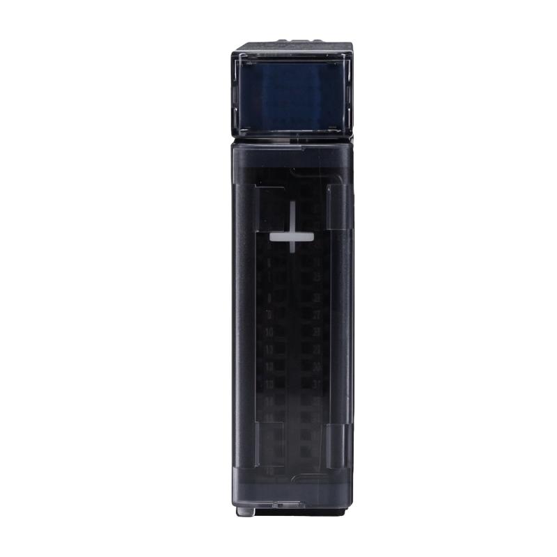
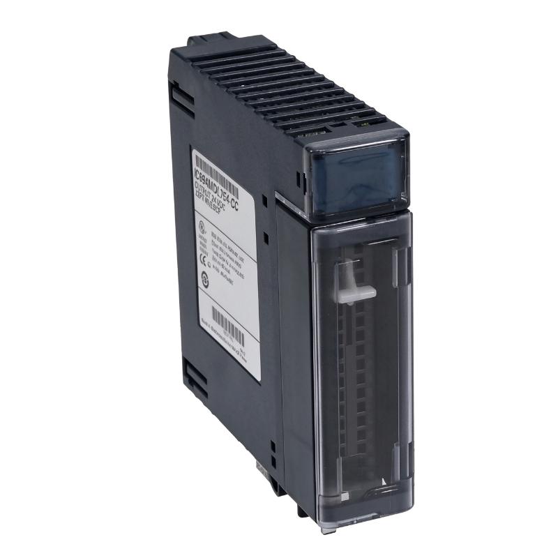
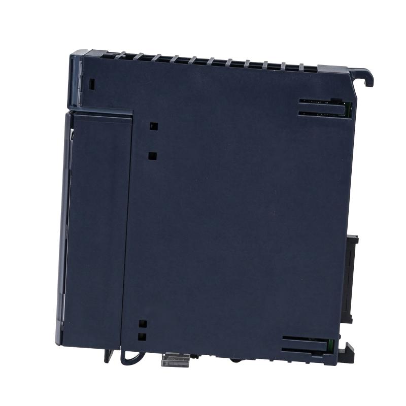
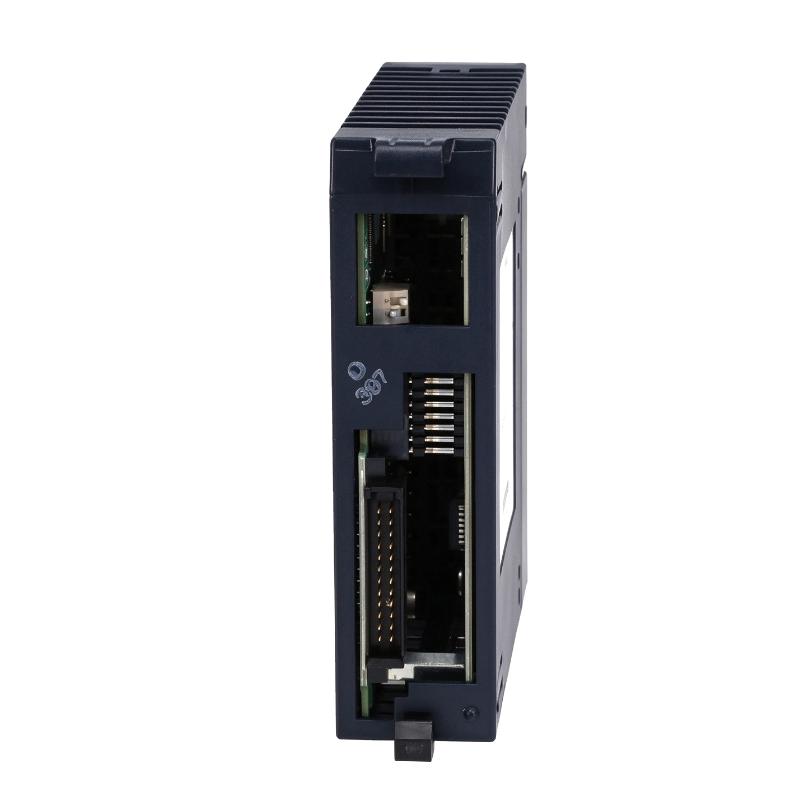
- GE
- IC695MDL754
- DC Voltage Discrete Output Module
- USA
- 145 x 34 x 140 mm
- 0.25 kg
- Xiamen, China
- New & In Stock
- T/T, PayPal, Western Union
- 1 Year
- 1-3 Working Days
- DHL, UPS, TNT, FedEx and EMS.
- 24-Hour Service
- COO
- 2
Our advantage

Global Logistics
We have a 10-year logistics and express cooperation agreement, so our products can be shipped to any place in the world.

Brand new and original
Our products are imported in bulk from the place of origin. Because of the cooperative relationship, our products are all original and 100% new.

24-hour service
We provide 7*24 hours service to our customers. We will be there whenever you need us.

Price advantage
All our products are priced very favorably because we have our own warehouse and supply.
| Company Information | |||
| [email protected] | |||
| Mobile | +8615980777398 | ||
| +8615980777398 | |||
| 15980777398 |
Product Overview
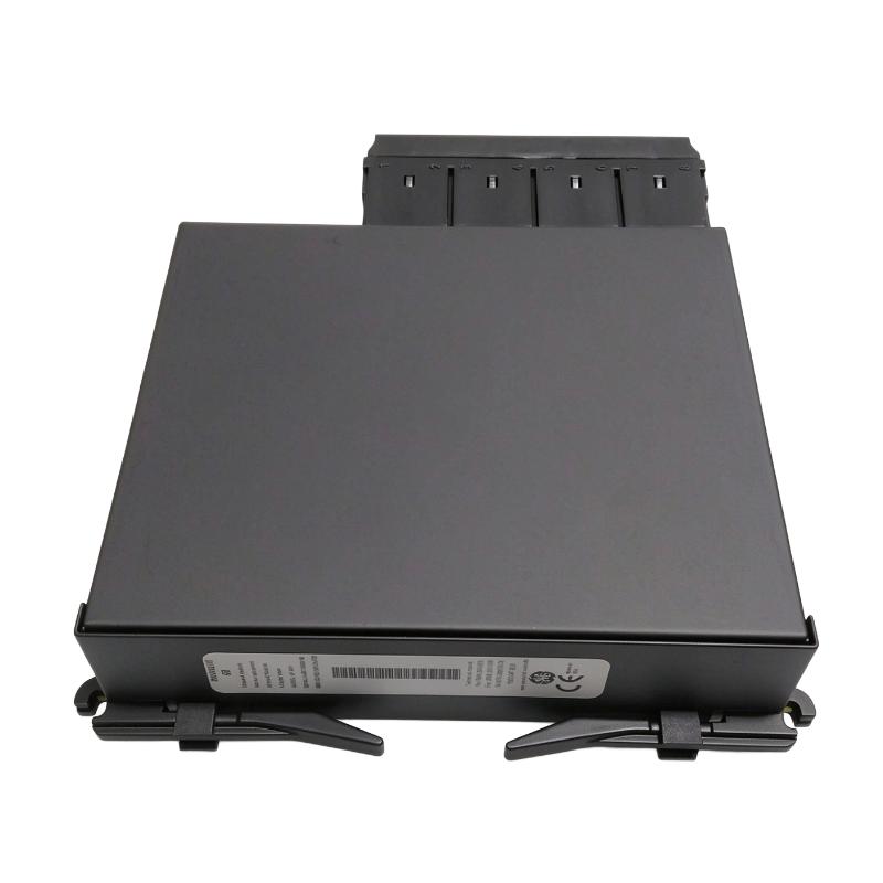
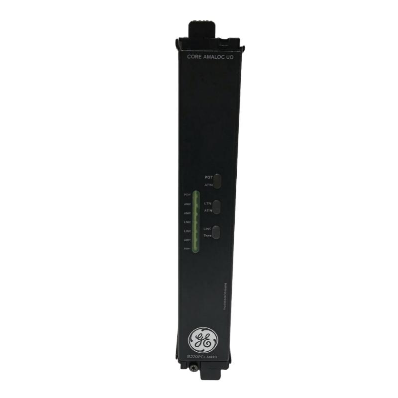
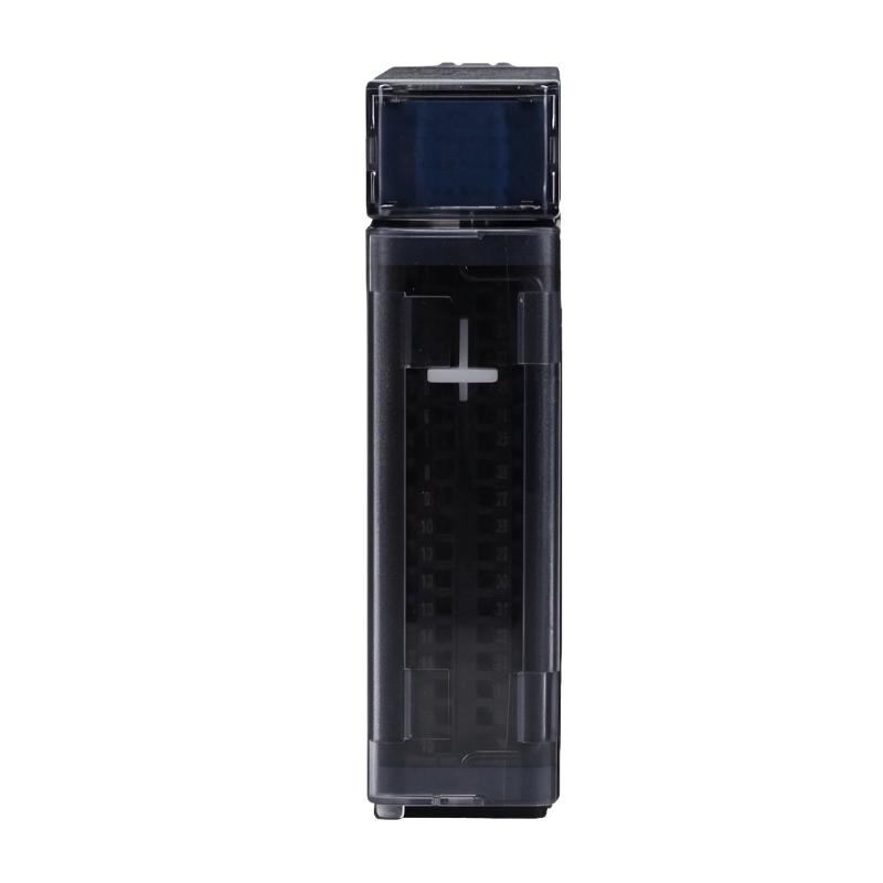
The GE IC695MDL754 DC Voltage Discrete Output Module is an industrial automation component identified for use in programmable logic controller (PLC) output applications. Discrete output modules provide the interface between a PLC control system and external field devices, allowing programmed logic to control electrical signals for connected equipment.
In an industrial automation system, a PLC processes input signals, executes its control program, and sends output commands to field devices. These commands may be used to operate relays, indicator lamps, solenoid valves, contactors, and other compatible electrical loads.
A DC voltage discrete output module is designed to switch DC output signals according to the controller’s instructions. Its suitability for a particular installation depends on the output voltage range, current capacity, number of channels, output logic, isolation, and protection characteristics.
The IC695MDL754 catalog number should be verified carefully before installation or replacement. Detailed technical documentation available for the similar IC694MDL754 model must not automatically be applied to IC695MDL754. The complete model number and hardware revision should be checked against the actual module label and the applicable GE documentation.
For industrial maintenance teams, accurate identification is especially important when replacing PLC output modules. A module with a similar product description may have different electrical characteristics, terminal arrangements, and controller compatibility.
Technical Specifications
| Parameter | Specification |
|---|---|
| Brand | GE |
| Product Model | IC695MDL754 |
| Product Type | DC Voltage Discrete Output Module |
| Product Category | PLC Digital Output Module |
| Output Signal Type | DC discrete output |
| PLC Platform Compatibility | Must be confirmed against the exact catalog number |
| Output Channel Count | Verify from the module nameplate and applicable datasheet |
| Rated Output Voltage | Verify from the exact IC695MDL754 documentation |
| Output Current | Verify from the exact IC695MDL754 documentation |
| Output Logic | Verify before wiring |
| Isolation | Verify from the exact hardware documentation |
| Protection Functions | Verify from the exact hardware documentation |
| Dimensions Provided | 145 × 34 × 140 mm |
| Weight Provided | 0.25 kg |
| Application | PLC-based industrial automation and discrete device control |
Important model distinction: IC694MDL754 is a separately identified model. Its published specifications include 32 outputs, 12/24 V DC nominal operation, a 10.2–30 V DC output range, and 0.75 A per point. These values should not be treated as confirmed specifications for IC695MDL754 without matching manufacturer documentation.
Function and Working Principle
A discrete output module converts the PLC’s internal control decisions into electrical output signals. These signals allow the automation system to control external devices according to the machine sequence or process requirements.
1. PLC Output Signal Processing
The PLC executes its control program using information received from input modules, communication devices, and internal logic. When an output condition is satisfied, the controller updates the corresponding output command.
The discrete output module receives this command through the controller’s backplane or supported system interface and switches the appropriate field output.
For example, a PLC may activate an output when a sensor detects that a product has reached a specific position. The output module then provides the electrical switching signal required by the connected actuator or control circuit.
2. DC Output Switching
DC discrete output modules are commonly used to control equipment that operates with low-voltage DC signals.
Depending on the module design, the output circuitry may use transistor-based switching or another specified output technology. The actual output type must be confirmed before connecting field loads.
Correct voltage and current matching is essential. A load that exceeds the module’s permitted output current may cause overheating, protection trips, or permanent damage.
3. Field Device Control
The output module provides a connection between PLC logic and external devices. Typical applications include:
- Operating compatible solenoid valves.
- Switching relay coils.
- Controlling indicator lamps.
- Activating auxiliary control circuits.
- Sending discrete commands to machine equipment.
The electrical characteristics of every connected load must be checked before commissioning.
4. Output Status and Diagnostics
Depending on the exact module design and controller configuration, output status may be monitored through module indicators, controller diagnostics, or engineering software.
These functions help maintenance personnel identify output-state conditions and investigate possible wiring or field-device problems.
Diagnostic capabilities should be confirmed from the correct product documentation rather than assumed from a similar model.
Role in Industrial Control Systems
The GE IC695MDL754 is identified as a discrete output module for industrial PLC applications. Its intended role is to provide controlled electrical switching between the automation controller and external equipment.
PLC System Integration
In a PLC-based control architecture, the controller executes the application program and coordinates the operation of connected I/O modules.
The output module receives control commands and provides the corresponding electrical signals to field devices. This arrangement allows the controller to manage machine sequences, equipment interlocks, and process operations.
Before integration, confirm the exact controller platform, compatible backplane, supported module revisions, and configuration requirements.
Field Device Coordination
Industrial machines often contain multiple devices that must operate in a coordinated sequence. Output modules allow the PLC to control these devices through programmed logic.
For example, a packaging machine may use output signals to activate a valve, operate an indicator, or enable an auxiliary relay after a specific process condition has been satisfied.
System Monitoring and Maintenance
PLC engineering software can help maintenance personnel monitor controller status and troubleshoot output-related problems. Depending on the installed hardware and software, technicians may be able to compare commanded output states with module or field-device indications.
Accurate module identification and wiring documentation make troubleshooting more efficient.
Industrial Applications
Discrete output modules are used in a wide range of industrial automation environments. The following examples describe typical applications of DC PLC output modules. Actual suitability of IC695MDL754 must be confirmed against its electrical specifications.
1. Manufacturing Automation
Manufacturing equipment uses discrete output signals to coordinate individual machine operations. PLC outputs may control auxiliary relays, indicator lights, pneumatic valves, and other devices.
A suitable output module helps the PLC execute programmed production sequences and coordinate equipment operation.
2. Packaging Machinery
Packaging lines frequently rely on discrete signals to operate pneumatic actuators, product guides, feeding mechanisms, and auxiliary equipment.
The PLC can activate the appropriate output when a product reaches a defined position or when a machine sequence advances to its next step.
3. Material Handling Systems
Conveyor systems and material-handling equipment use discrete outputs to control auxiliary devices, alarms, indicators, and switching circuits.
PLC-based output control helps coordinate equipment movement and respond to signals from sensors and other automation components.
4. Process Automation
Industrial process systems often require discrete control of valves, auxiliary relays, alarms, and equipment enable signals.
An appropriately selected DC output module can provide the electrical interface between the PLC and these field devices.
5. Equipment Monitoring and Auxiliary Control
Discrete output signals can also be used for status indication, auxiliary equipment activation, and control-system interlocking.
The final application must account for the output module’s electrical limits and the requirements of the connected devices.
Installation and System Integration
Correct installation is essential for reliable PLC operation. Before installing the IC695MDL754, verify its exact product identity and follow the documentation for the corresponding hardware revision.
1. Confirm Model and Controller Compatibility
Check the complete catalog number on the module label. Confirm that the controller platform, backplane, firmware, and engineering software support the module.
Do not assume that a module with a similar number or description is interchangeable.
2. Verify Electrical Requirements
Before connecting field wiring, confirm:
- Rated DC output voltage.
- Permitted output voltage range.
- Maximum current per channel.
- Maximum current per group.
- Output logic and switching type.
- Required external field power supply.
- Isolation and grounding requirements.
These details determine which field devices can be connected safely.
3. Install the Module Correctly
Follow the manufacturer’s instructions for module insertion, mounting, and removal. Ensure that the controller is in the required safe state before performing installation work.
Avoid forcing the module into its slot or making connections while the system is energized unless the hardware documentation explicitly permits that procedure.
4. Connect Field Wiring
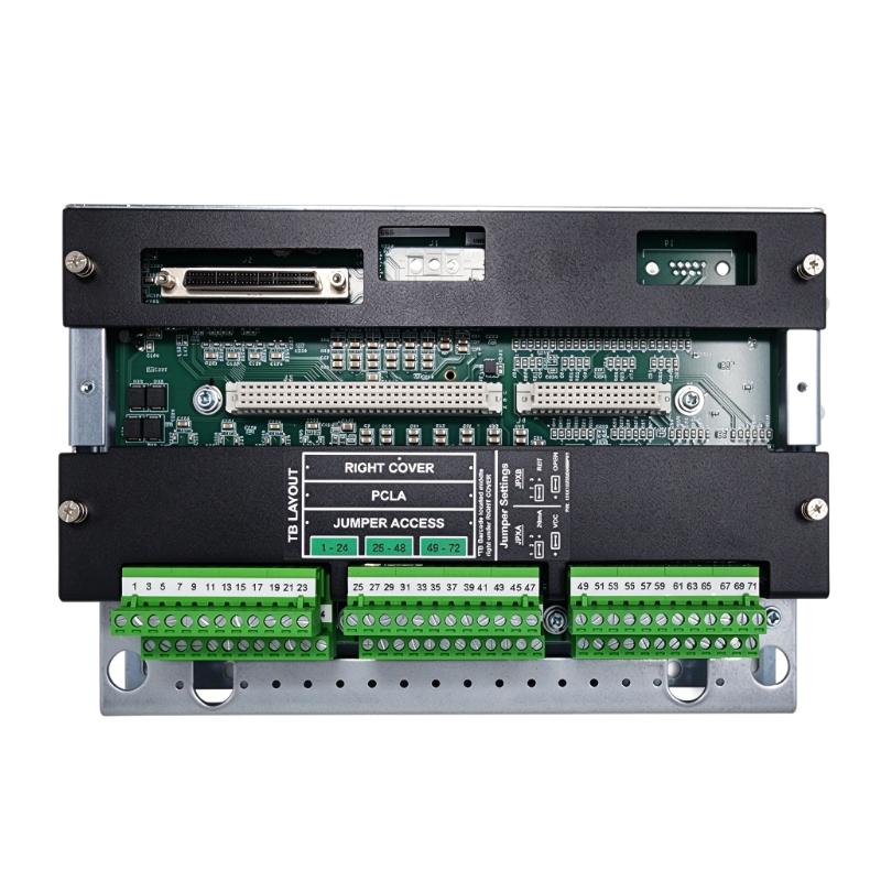
Use the correct terminal block, connector, or wiring assembly specified for the exact module. Confirm terminal assignments before connecting output devices.
Separate signal wiring from power conductors where required, and use appropriate grounding and cable-routing practices to reduce electrical interference.
5. Configure and Test Outputs
After installation, configure the module in the PLC engineering environment if required. Verify the module’s recognition status and confirm that the configured output points match the actual wiring.
Test each required output under controlled conditions. Confirm that connected devices respond correctly and that no unexpected output activation occurs.
6. Document the Installation
Record the module catalog number, hardware revision, terminal assignments, connected loads, and PLC configuration.
Accurate documentation simplifies future troubleshooting and helps prevent incorrect substitutions during maintenance.
Compatible System Components
A PLC output module operates as part of a wider automation system. The following components may be used in a typical installation, subject to confirmation of the exact IC695MDL754 requirements.
| Component | Function | Integration Considerations |
|---|---|---|
| Compatible PLC CPU | Executes the automation program | Confirm support for the exact module |
| PLC backplane or rack | Provides module mounting and system connections | Verify platform and slot compatibility |
| DC field power supply | Supplies the required field-side power | Match the module’s documented voltage and current requirements |
| Terminal block or connector | Provides field wiring connections | Use the correct part for the exact module |
| Interposing relay | Interfaces with loads requiring different electrical characteristics | Select suitable coil voltage and contact ratings |
| Solenoid valve | Performs pneumatic or fluid-control operations | Verify voltage, current, and suppression requirements |
| Indicator lamp | Provides machine or process status indication | Confirm DC voltage and load current |
| Engineering software | Configures and monitors the PLC system | Check supported hardware and software versions |
| Field wiring | Connects the output module to external devices | Follow terminal assignments and wiring specifications |
The components listed above are typical elements of PLC output installations. They are not necessarily included with the module.
Alternative Models and Replacement Considerations
When replacing a PLC output module, engineers should compare the complete electrical and mechanical specifications rather than relying on a similar product name.
| Alternative or Related Model | Description | Replacement Considerations |
|---|---|---|
| GE IC694MDL754 | 32-point 12/24 V DC output module | Separate catalog number; do not assume direct compatibility |
| GE IC694MDL753 | 32-point 12/24 V DC positive-logic output module | Compare current rating, output logic, and controller compatibility |
| GE IC694MDL752 | 32-point DC output module | Verify voltage range, output logic, and electrical characteristics |
| GE IC694MDL742 | 16-point 12/24 V DC output module | Different channel count and output configuration |
| GE IC695MDL740 | RX3i discrete output module | Confirm electrical ratings and system compatibility |
Before choosing a replacement, compare the following:
- Complete catalog number and hardware revision.
- Controller and backplane compatibility.
- Output voltage range.
- Number of output points.
- Current rating per output.
- Group current limitations.
- Positive or negative output logic.
- Isolation characteristics.
- Short-circuit and overcurrent protection.
- Terminal block and wiring requirements.
- Configuration and software support.
A module with a different channel count or output logic may require changes to the wiring, PLC configuration, or control program.
Key Advantages of DC Discrete Output Modules
Direct PLC-to-Field Control
Discrete output modules provide the electrical interface needed for a PLC to control external equipment through programmed logic.
Support for Automated Sequences
PLC outputs allow field devices to operate in a coordinated sequence based on sensor feedback, internal logic, and process conditions.
Modular System Architecture
A modular I/O design allows control-system functions to be organized according to the requirements of the installation.
Flexible Field Device Applications
Depending on their electrical specifications, DC output modules can control a range of industrial devices, including relays, indicators, and solenoid valves.
Easier Maintenance and Troubleshooting
Clearly identified output points and proper PLC documentation help maintenance personnel locate control signals and investigate field-device problems.
Technical FAQs
1. What is the GE IC695MDL754?
It is identified as a GE DC voltage discrete output module for PLC-based industrial automation applications. Its exact electrical specifications and platform compatibility should be confirmed using the manufacturer’s documentation for the complete catalog number.
2. What is a DC discrete output module used for?
It allows a PLC to switch DC electrical signals to external devices. Common applications include controlling relay coils, solenoid valves, indicators, and auxiliary machine-control circuits.
3. How many output points does the IC695MDL754 have?
The output channel count should be confirmed from the exact IC695MDL754 datasheet or module label. Do not use the channel count of the similarly named IC694MDL754 as a substitute.
4. What output voltage does this module support?
The rated voltage and permitted output range must be checked against the IC695MDL754 documentation before wiring. Similar catalog numbers may have different electrical specifications.
5. Can the module control solenoid valves?
A DC output module may control compatible solenoid valves when the voltage, current, switching characteristics, and protection requirements are within its ratings. Confirm the IC695MDL754’s exact output specifications first.
6. How do I identify a faulty output channel?
Check the PLC output command, module status, field wiring, external power supply, and connected load. Follow the manufacturer’s diagnostic procedures and isolate the system before carrying out electrical inspections.
7. Can IC695MDL754 replace IC694MDL754?
They should not be treated as interchangeable based on their similar catalog numbers. Confirm controller compatibility, electrical specifications, connector arrangements, and manufacturer replacement guidance before substitution.
8. What should I check before purchasing this module?
Verify the complete catalog number, hardware revision, physical condition, terminal or connector condition, and compatibility with the installed PLC system. Request clear product-label photographs when sourcing replacement equipment.
9. What are the dimensions and weight?
The supplied listing information gives dimensions of 145 × 34 × 140 mm and a weight of 0.25 kg. Verify these values against the actual unit before calculating shipping or installation requirements.
10. Why is exact model verification important?
PLC modules with similar descriptions may use different output voltages, current ratings, channel configurations, and controller platforms. Incorrect selection can cause configuration errors, unreliable operation, or damage to connected equipment.
Procurement and Maintenance Recommendations
When purchasing the GE IC695MDL754, begin by confirming the complete model number on the module’s nameplate. This is particularly important because detailed information for the similarly named IC694MDL754 can easily be confused with information for IC695MDL754.
For replacement projects, compare the installed module with the proposed replacement using the original system documentation. Verify controller compatibility, output voltage, channel count, current capacity, output logic, terminal arrangement, and protection characteristics.
For used or surplus modules, inspect the housing, connector, terminals, and visible electronic components. Request photographs of the nameplate and ask for available functional-test information. Confirm the supplied accessories and the applicable warranty and return conditions.
During routine maintenance, inspect field wiring, terminal connections, external power supplies, and connected loads. Investigate recurring output faults rather than repeatedly resetting the system without identifying the underlying cause.
Keep a record of module revisions, PLC configuration, wiring assignments, and replacement history. This information helps reduce downtime and supports more reliable maintenance planning.
Conclusion
The GE IC695MDL754 DC Voltage Discrete Output Module is identified as an industrial PLC output component for controlling external devices through discrete DC signals. It can be considered for applications involving machine control, manufacturing automation, material handling, and process equipment, subject to verification of its exact technical specifications.
For accurate product selection and safe system integration, the complete catalog number and hardware revision must be checked against the manufacturer’s documentation. In particular, IC695MDL754 should not be confused with the separately identified IC694MDL754. Confirming the correct module before installation helps prevent electrical mismatches and unnecessary downtime in industrial automation systems.