

ProductPRODUCT
Featured products
Contact Us
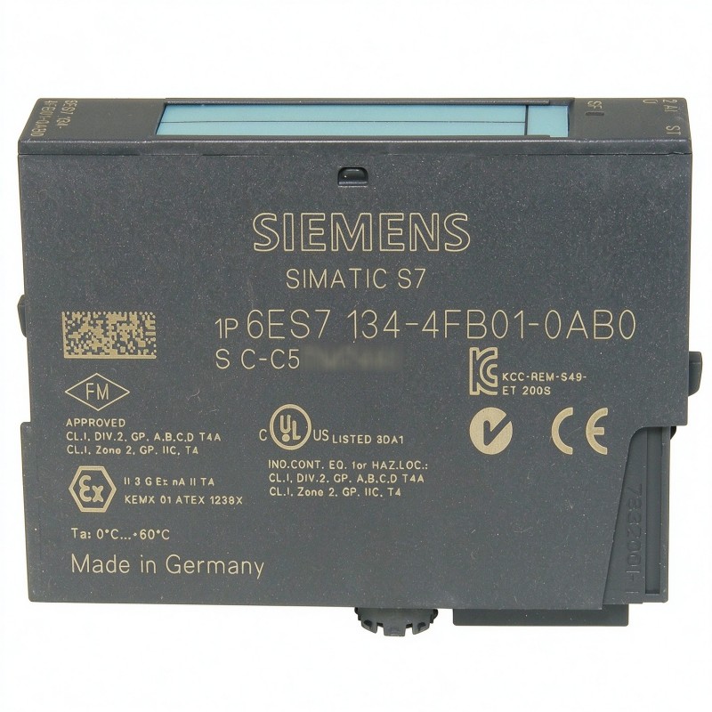
- Siemens
- 6ES7134-4FB01-0AB0
- Analog Input Module
- Germany
- 15 × 81 × 52 mm
- 0.045 kg
- Xiamen, China
- New & In Stock
- T/T, PayPal, Western Union
- 1 Year
- 1-3 Working Days
- DHL, UPS, TNT, FedEx and EMS.
- 24-Hour Service
- COO
- 24
Our advantage

Global Logistics
We have a 10-year logistics and express cooperation agreement, so our products can be shipped to any place in the world.

Brand new and original
Our products are imported in bulk from the place of origin. Because of the cooperative relationship, our products are all original and 100% new.

24-hour service
We provide 7*24 hours service to our customers. We will be there whenever you need us.

Price advantage
All our products are priced very favorably because we have our own warehouse and supply.
| Company Information | |||
| [email protected] | |||
| Mobile | +8615980777398 | ||
| +8615980777398 | |||
| 15980777398 |
Product Overview
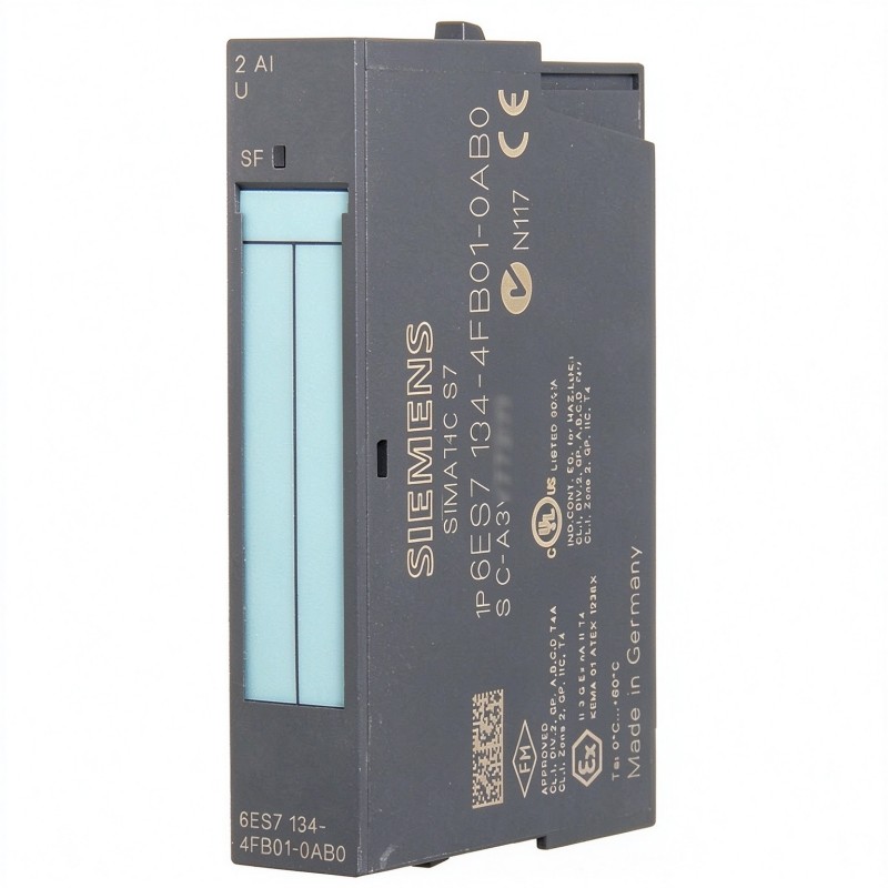
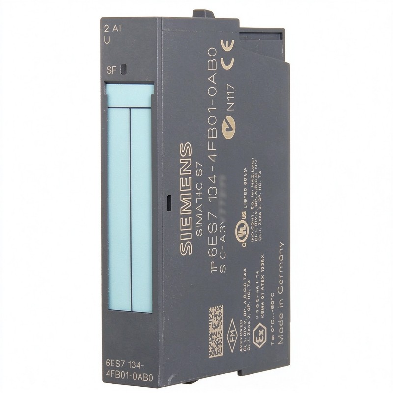
The Siemens 6ES7134-4FB01-0AB0 SIMATIC ET 200S Analog Input Module is a two-channel analog voltage input module used in distributed automation systems. It acquires continuous voltage signals from field instruments and converts them into digital measurement values for processing by a SIMATIC controller.
This module belongs to the ET 200S distributed I/O family and occupies a 15 mm installation position. Its two input channels support three selectable voltage ranges: ±10 V, ±5 V, and 1–5 V. This makes it suitable for connecting voltage-output sensors and measuring instruments used in machine control and process monitoring.
A typical application involves collecting pressure or temperature measurements from field transmitters that provide voltage signals. For example, a pressure transmitter connected to one channel can send a changing voltage corresponding to the pressure inside a pipeline. The module converts this signal into a numerical value that the PLC can use for process monitoring, alarm generation, or control logic.
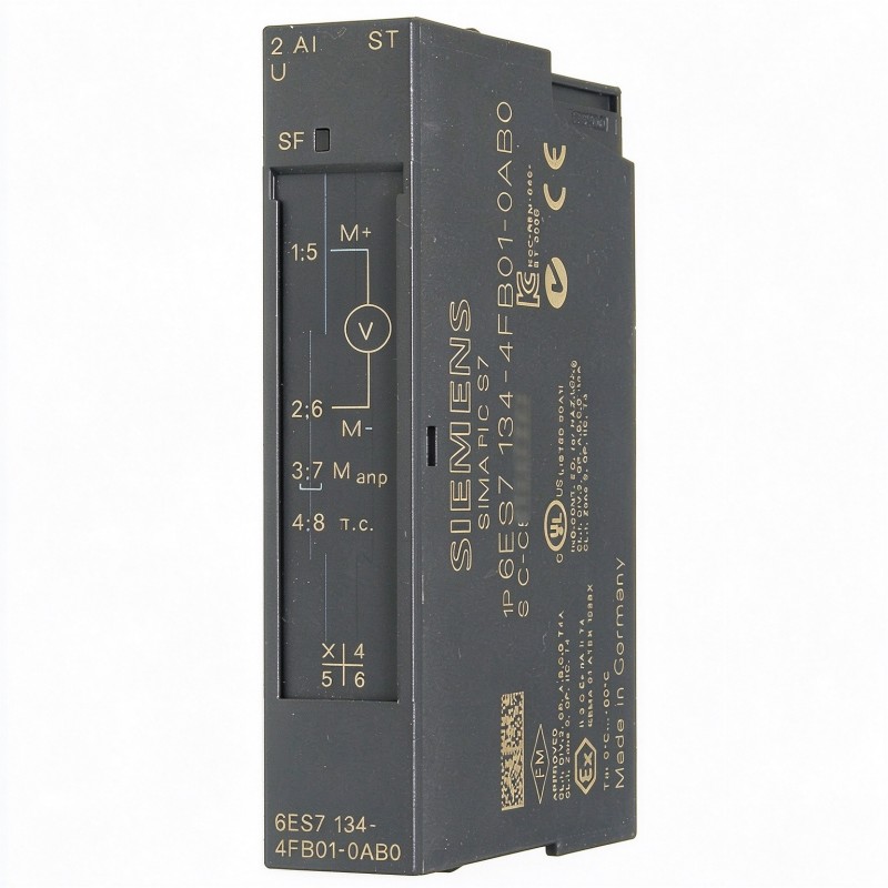
The 6ES7134-4FB01-0AB0 is identified as the 2AI U ST analog electronic module. Its standard input configuration is intended for voltage measurements rather than direct current-loop acquisition. This distinction matters when selecting field instruments: a transmitter with a 4–20 mA output requires an appropriate current-input interface or a suitable signal conversion arrangement.
The module uses an integrating measurement principle and supports parameterizable integration times. Its conversion time is approximately 65 ms per channel under the specified operating configuration. This makes it suitable for process measurements where dependable analog acquisition is more important than extremely fast signal response.
A red SF LED provides group fault indication. The module also supports diagnostic functions such as wire-break detection in the 1–5 V measuring range and overrange or underrange monitoring.
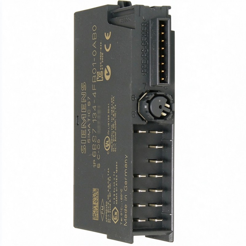
In an ET 200S station, the module works with the corresponding terminal module and backplane bus arrangement. Its narrow 15 mm width allows two analog measurement channels to be incorporated into a compact distributed I/O assembly.
Technical Specifications
| Parameter | Specification |
|---|---|
| Manufacturer | Siemens |
| Model | 6ES7134-4FB01-0AB0 |
| Product Type | Analog Input Module |
| Product Family | SIMATIC ET 200S |
| Module Designation | 2AI U ST |
| Number of Analog Inputs | 2 |
| Input Signal Type | Voltage |
| Input Ranges | ±10 V, ±5 V, 1–5 V |
| Resolution | 13 bit + sign (±10 V and ±5 V); 12 bit + sign (1–5 V) |
| Conversion Time | 65 ms per channel |
| Measurement Principle | Integrating |
| Supply Voltage | 24 V DC (from power module) |
| Power Consumption | 0.6 W |
| Maximum Address Space | 4 bytes |
| Diagnostic Indication | SF LED (Group Fault) |
| Protection Rating | IP20 |
| Dimensions | 15 × 81 × 52 mm |
| Weight | 0.045 kg |
Product Features
- Two Voltage Input Channels: Acquires two independent analog voltage signals within one compact module.
- Multiple Measuring Ranges: Supports ±10 V, ±5 V, and 1–5 V input configurations.
- High-Resolution Conversion: Provides up to 13 bit + sign resolution for the bipolar voltage ranges.
- Integrating Measurement Principle: Uses integration-based measurement for analog signal acquisition.
- Configurable Integration Time: Allows measurement integration settings to be adjusted according to application requirements.
- Group Fault Indication: The SF LED provides a visual indication of module-level diagnostic conditions.
- Wire-Break Monitoring: Supports wire-break diagnostics when operating in the 1–5 V measuring range.
- Compact 15 mm Width: Fits the narrow ET 200S module arrangement.
- Potential Isolation: Provides electrical isolation between the analog input circuitry and the backplane bus and load voltage.
Working Principle
The 6ES7134-4FB01-0AB0 receives voltage signals from connected field instruments and converts them into digital values that can be read by the SIMATIC controller.
The acquisition process follows this general sequence:
Field Voltage Sensor → ET 200S Terminal Module → 6ES7134-4FB01-0AB0 → Analog-to-Digital Conversion → Backplane Bus → PLC
When a field instrument measures a physical variable such as pressure, temperature, or liquid level, it generates a corresponding voltage signal. This signal enters one of the module’s two analog input channels through the associated terminal arrangement.
The module measures the incoming voltage according to the selected input range. Depending on the application, the channel can be configured for ±10 V, ±5 V, or 1–5 V.
The integrating measurement process evaluates the incoming signal over a defined period. This helps suppress certain electrical disturbances and produces a digital representation of the measured voltage.
After conversion, the resulting analog value is transferred through the ET 200S backplane bus to the higher-level controller. The PLC can then apply scaling, compare the measurement against configured limits, and execute the corresponding control logic.
For example, in a water treatment installation, one channel may acquire a voltage signal from a pressure transmitter monitoring a filtration pipeline, while the second channel measures another process variable. The controller receives both measurements and can generate an alarm if either value exceeds its configured operating range.
The module’s diagnostic functions also support fault identification. In the 1–5 V range, wire-break monitoring can help identify an interrupted sensor connection. Overrange and underrange diagnostics provide additional information when the measured signal falls outside the configured measurement limits.
The conversion time of approximately 65 ms per channel should be considered when configuring applications involving changing process values. It is more appropriate for general process monitoring than applications requiring very high-speed analog sampling.
Role in the SIMATIC ET 200S Distributed I/O Architecture
The 6ES7134-4FB01-0AB0 serves as the analog measurement interface between field instruments and the ET 200S distributed I/O station. It converts external voltage signals into digital process values that can be accessed by the central controller.
A typical signal path follows this arrangement:
Voltage Transmitters → ET 200S Terminal Module → 6ES7134-4FB01-0AB0 → ET 200S Backplane Bus → Interface Module → SIMATIC PLC
| System Component | Function |
|---|---|
| Field Voltage Transmitter | Converts a physical process variable into a voltage signal |
| ET 200S Terminal Module | Provides the electrical connection for the analog input module |
| 6ES7134-4FB01-0AB0 | Acquires two analog voltage signals and converts them into digital values |
| ET 200S Backplane Bus | Transfers module data within the distributed I/O station |
| Interface Module | Connects the ET 200S station to the higher-level automation network |
| SIMATIC PLC | Processes acquired measurement values and executes control logic |
| 24 V DC Power Module | Supplies the required station load voltage |
| Shield Connection | Supports proper shielding of analog signal cables |
| Field Instrumentation | Provides pressure, temperature, level, or other process measurements |
The module does not directly accept every type of analog transmitter output. Its voltage-input configuration must match the electrical output of the connected instrument.
For installations using 4–20 mA transmitters, an appropriate current-input module or signal conversion device is required. Connecting a current-loop instrument without considering the input configuration can result in incorrect measurements or an unsuitable electrical interface.
The terminal module and wiring arrangement must also be selected according to the ET 200S system configuration. Correct shielding and grounding are particularly important when measuring low-level analog signals in industrial environments with electrical noise.
Industrial Applications
| Application | Typical Use |
|---|---|
| Water Treatment Plants | Acquiring voltage signals from pressure and level transmitters |
| Chemical Processing | Monitoring process variables through voltage-output instrumentation |
| Manufacturing Lines | Collecting analog measurements for machine monitoring |
| Pumping Stations | Monitoring pressure and operating conditions |
| HVAC Systems | Acquiring voltage signals from temperature and pressure sensors |
| Food and Beverage Production | Monitoring process conditions through analog instrumentation |
| Pharmaceutical Manufacturing | Collecting measurement signals for process supervision |
| Packaging Machinery | Monitoring analog operating variables within machine control systems |
| Power Generation | Acquiring auxiliary process measurement signals |
| Industrial Utilities | Integrating voltage-output instruments into distributed control systems |
Installation and Maintenance
- Verify the Module Number: Confirm that 6ES7134-4FB01-0AB0 matches the intended ET 200S configuration and that two voltage input channels are sufficient for the application.
- Check the Input Signal Type: Verify that the connected transmitters provide voltage outputs compatible with the module. Do not assume that a standard 4–20 mA signal can be connected directly.
- Prepare the ET 200S Station: Confirm that the correct terminal module, power module, and interface module are installed before fitting the analog input module.
- Isolate the Power Supply: Disconnect the relevant supply according to the site’s electrical safety procedures before installing or removing the module.
- Inspect the Terminal Module: Check the terminal contacts and mounting area for contamination, deformation, or damaged connections.
- Install the Analog Input Module: Position the 6ES7134-4FB01-0AB0 on the designated ET 200S terminal module and secure it according to the system installation procedure.
- Connect the Analog Signals: Wire the two field voltage signals to their assigned input terminals. Observe the correct polarity and channel assignments.
- Configure the Measuring Range: Select ±10 V, ±5 V, or 1–5 V for each applicable channel according to the connected transmitter’s output specification.
- Check Shielding and Grounding: Ensure that analog signal cables are shielded and routed appropriately. Poor shielding or grounding can introduce measurement disturbances.
- Configure Diagnostic Functions: Set the required wire-break and group diagnostic parameters. Wire-break monitoring is available in the 1–5 V measuring range.
- Test the Measurement Values: Restore the supply and verify the input readings using known reference signals. Check both channels and confirm that the PLC receives the expected digital values.
- Record the Configuration: Document the input ranges, connected instruments, channel assignments, diagnostic settings, and module identification for future maintenance.
Compatible System Components
| Component | Function |
|---|---|
| Siemens 6ES7134-4FB01-0AB0 | Two-channel analog voltage input module |
| Siemens 6ES7138-4CA01-0AA0 | ET 200S Power Module |
| Siemens 6ES7151-1AA05-0AB0 | ET 200S IM151-1 Interface Module |
| Siemens 6ES7134-4GB01-0AB0 | ET 200S Analog Input Module, 2 AI Standard I |
| Siemens 6ES7134-4FB52-0AB0 | ET 200S Analog Input Module, 2 AI High Feature |
| SIMATIC ET 200S Terminal Module | Provides the electrical connection and mounting interface |
| 24 V DC Power Supply | Supplies operating power to the distributed I/O station |
| Analog Voltage Transmitters | Provide voltage measurement signals |
| Shielded Signal Cable | Carries analog signals while reducing electrical interference |
Recommended Related Models
| Model | Product Type | Typical Application |
|---|---|---|
| Siemens 6ES7134-4GB01-0AB0 | SIMATIC ET 200S Analog Input Module | Two-channel current input acquisition |
| Siemens 6ES7134-4FB52-0AB0 | SIMATIC ET 200S Analog Input Module | High-feature analog voltage acquisition |
| Siemens 6ES7134-4JB01-0AB0 | SIMATIC ET 200S Analog Input Module | Four-channel analog voltage acquisition |
| Siemens 6ES7135-4FB01-0AB0 | SIMATIC ET 200S Analog Output Module | Analog voltage output control |
| Siemens 6ES7138-4CA01-0AA0 | SIMATIC ET 200S Power Module | Distributed I/O load voltage supply |
| Siemens 6ES7151-1AA05-0AB0 | SIMATIC ET 200S Interface Module | Connection to the distributed I/O network |
Key Advantages
- Two analog voltage input channels in a 15 mm module.
- Supports ±10 V, ±5 V, and 1–5 V measuring ranges.
- Up to 13 bit + sign resolution for bipolar voltage measurements.
- Integrating measurement principle with configurable integration time.
- Group fault indication through the SF LED.
- Wire-break diagnostics in the 1–5 V range.
- Potential isolation between the analog inputs and backplane bus.
- Integration into SIMATIC ET 200S distributed I/O stations.
Technical FAQs
Can the 6ES7134-4FB01-0AB0 directly measure 4–20 mA signals?
No. This module is a voltage-input version with selectable ranges of ±10 V, ±5 V, and 1–5 V. For a 4–20 mA transmitter, an appropriate current-input module such as the ET 200S 2AI current-input version should be selected, or a suitable signal conversion arrangement must be used.
What is the difference between the ±10 V and 1–5 V measuring ranges?
The ±10 V range supports bipolar voltage measurements, making it suitable for signals that can move above and below zero. The 1–5 V range is intended for unipolar measurement signals and additionally supports wire-break diagnostics. The resolution also differs between these ranges.
What does the SF LED indicate on the 6ES7134-4FB01-0AB0?
The SF LED is the module’s group fault indicator. When illuminated, it indicates a diagnostic or fault condition that requires investigation. The configured diagnostic information and PLC diagnostic records should be checked to identify the specific issue.
Is the 6ES7134-4FB01-0AB0 suitable for fast-changing analog signals?
The module has a conversion time of approximately 65 ms per channel. It is suitable for conventional process measurement and monitoring, such as pressure and temperature acquisition. Applications requiring rapid analog response or high-frequency sampling should use a module with specifications appropriate to those requirements.