

ProductPRODUCT
Featured products
Contact Us
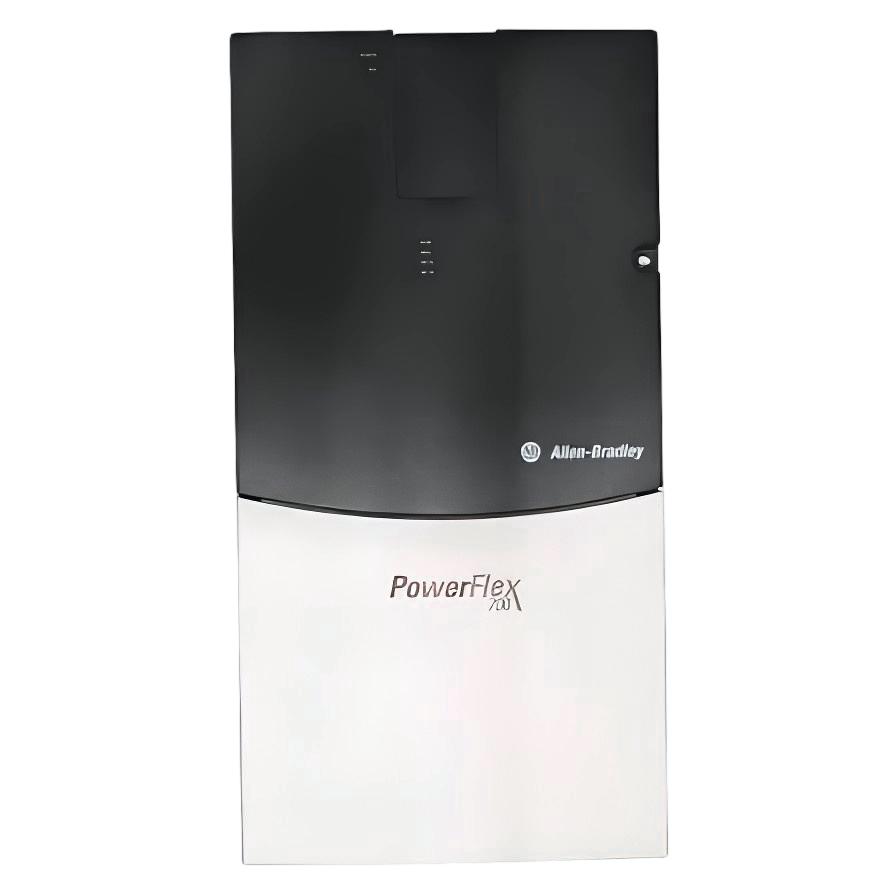
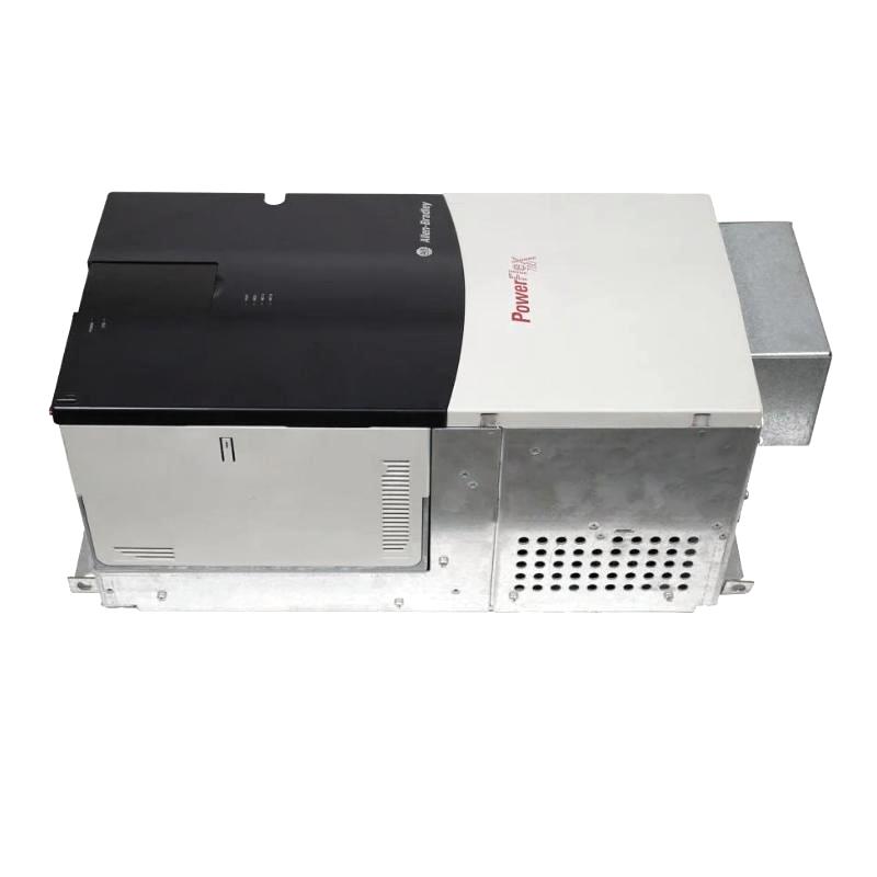
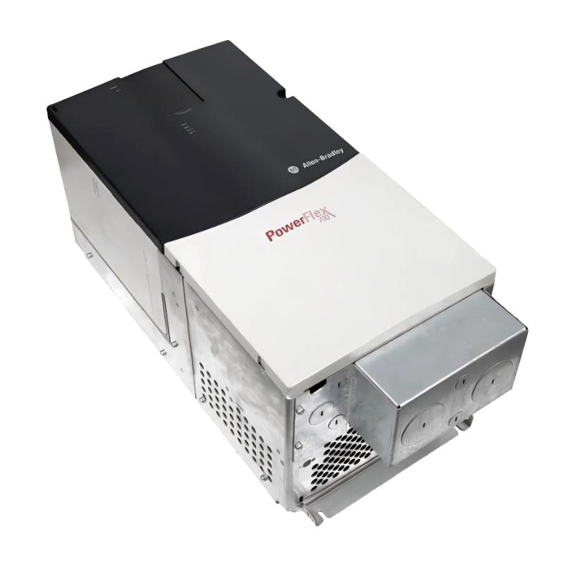
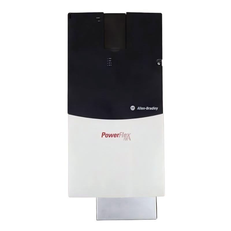
- Allen Bradley
- 20BB154A3ANNANC0
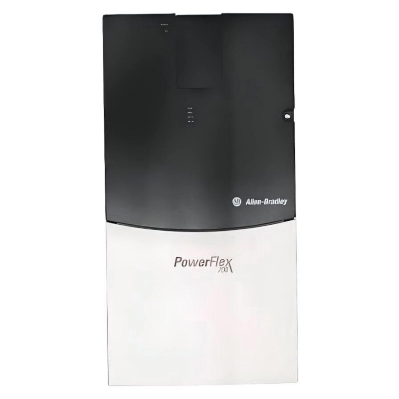
- PowerFlex 700 AC Drive
- USA
- 976.3 × 403.9 × 275.5 mm
- 71.44 kg
- Xiamen, China
- New & In Stock
- T/T, PayPal, Western Union
- 1 Year
- 1-3 Working Days
- DHL, UPS, TNT, FedEx and EMS.
- 24-Hour Service
- COO
- 5
Our advantage

Global Logistics
We have a 10-year logistics and express cooperation agreement, so our products can be shipped to any place in the world.

Brand new and original
Our products are imported in bulk from the place of origin. Because of the cooperative relationship, our products are all original and 100% new.

24-hour service
We provide 7*24 hours service to our customers. We will be there whenever you need us.

Price advantage
All our products are priced very favorably because we have our own warehouse and supply.
| Company Information | |||
| [email protected] | |||
| Mobile | +8615980777398 | ||
| +8615980777398 | |||
| 15980777398 |
Product Overview
The Allen Bradley 20BB154A3ANNANC0 PowerFlex 700 AC Drive is an adjustable-frequency drive for industrial three-phase AC motor applications. This 240 V-class model has a rated output current of 154 A and is rated for 60 HP in normal-duty operation and 50 HP in heavy-duty operation. Its vector-control configuration and 24 V I/O support make it suitable for motor-control systems that require adjustable-speed operation and integration with external machine controls.
The drive regulates the electrical output supplied to an AC motor, allowing the motor to operate at a selected speed rather than running continuously at a fixed supply frequency. This capability is useful in production machinery where motor speed affects throughput, material movement, process flow, or the coordination of connected equipment.
The 20BB154A3ANNANC0 includes an LCD display and full numeric keypad for local interaction with the drive. These controls are useful during commissioning, parameter adjustment, and troubleshooting. Technicians can work with drive settings and operating information at the unit rather than relying entirely on an external controller.
Its vector-control configuration supports applications requiring more controlled motor response than basic fixed-frequency operation. The actual performance depends on the selected control settings, motor characteristics, and mechanical load. Correct motor data and appropriate operating parameters are therefore essential when bringing the drive into service.
The model’s 154 A current rating must be evaluated alongside the motor’s nameplate current and required operating duty. Normal-duty and heavy-duty applications impose different demands on the drive, so the appropriate power rating depends on the machine’s load profile, acceleration requirements, and expected overload conditions. The 60 HP normal-duty and 50 HP heavy-duty ratings provide useful selection criteria for compatible 240 V-class motor applications.
The catalog configuration also specifies that the drive does not include a Brake IGBT, an internal drive-mounted braking resistor, a communication module, or a feedback option. These characteristics matter when the application requires regenerative-energy handling, network-based control, or encoder feedback. The motor-control architecture should account for these requirements from the beginning rather than treating them as standard features.
In a conveyor system, the drive can regulate motor speed to coordinate material movement between production stages. In a pump or fan installation, it can adjust motor operation to match process demand. For machinery with more demanding torque requirements, the vector-control arrangement can be configured to suit the motor and load, subject to the drive’s operating limits.
The PowerFlex 700 can also form part of a PLC-controlled system. The PLC manages production sequences, interlocks, and process logic, while the drive regulates the motor according to the commands and parameters established for the application. The available control signals and external interfaces must be incorporated into the electrical design.
For installations involving frequent stopping or high-inertia loads, braking requirements deserve particular attention. A motor can return energy to the drive during deceleration, and the energy generated depends on the load and stopping profile. Since this configuration does not include a Brake IGBT or an internal drive-mounted braking resistor, the braking strategy must be selected according to the application and compatible external equipment.
The Allen Bradley 20BB154A3ANNANC0 PowerFlex 700 AC Drive is suited to applications that need adjustable-frequency motor control, local keypad access, and vector-control functionality. Its electrical ratings, installed options, and control requirements should be considered together when specifying the drive for industrial machinery.
Technical Specifications
| Parameter | Specification |
|---|---|
| Manufacturer | Allen Bradley |
| Model | 20BB154A3ANNANC0 |
| Product Family | PowerFlex 700 |
| Product Type | Adjustable Frequency AC Drive |
| Drive Series | 20B |
| Voltage Class | 240 V |
| Input Voltage | 200–240 V AC |
| Input Phase | 3-phase |
| Rated Output Current | 154 A |
| Normal-Duty Power Rating | 60 HP |
| Heavy-Duty Power Rating | 50 HP |
| Control Method | Vector Control |
| Control I/O | 24 V I/O |
| Human Interface | LCD Display with Full Numeric Keypad |
| Brake IGBT | Not included |
| Internal Drive-Mounted Braking Resistor | Not included |
| Communication Module | Not included |
| Feedback Option | Not included |
| Degree of Protection | IP20 / NEMA Type 1 |
| Conformal Coating | Included |
| Dimensions | 976.3 × 403.9 × 275.5 mm |
| Weight | 71.44 kg |
Product Features
- 154 A rated output current: Supports compatible motor applications with substantial current requirements.
- 60 HP normal-duty rating: Suits applications operating within the corresponding normal-duty limits.
- 50 HP heavy-duty rating: Defines the applicable power rating for more demanding operating conditions.
- Vector control: Supports controlled motor operation according to the selected configuration and motor parameters.
- 24 V I/O: Supports integration with compatible external control circuits.
- LCD display and full numeric keypad: Allows local access to drive settings and operating information.
- Conformal coating: Provides additional protection for the electronic assemblies under the specified environmental conditions.
- No integrated braking hardware: Requires the braking arrangement to be considered separately where the application demands it.
- No communication module or feedback option: Keeps the installed configuration distinct from variants equipped with those options.
- Industrial motor-control applications: Supports compatible conveyors, pumps, fans, and production machinery.
Working Principle
The PowerFlex 700 converts incoming three-phase AC power into a controlled electrical output for an AC motor. Its power-conversion hardware and vector-control functions regulate motor operation according to the selected control settings and operating reference.
Three-Phase AC Supply → Rectifier → DC Bus → Inverter → AC Motor
The rectifier converts the incoming AC supply into DC power. The DC bus provides the intermediate electrical link, and the inverter switches that power to generate an AC output with a controlled voltage and frequency. By regulating the output, the drive can adjust the connected motor’s operating speed.
Vector control uses motor-related parameters and control calculations to regulate motor behavior. Depending on the configured control mode and application, this approach can support improved torque response and speed regulation compared with simpler control arrangements. The resulting performance depends on the motor, the configured parameters, and the operating conditions.
The commissioning process begins with the motor’s nameplate data. Voltage, current, rated frequency, and other required motor information must be entered correctly. The selected control mode and operating limits should reflect the connected motor and mechanical load. Incorrect settings can lead to poor speed response, excessive current demand, or unexpected behavior during acceleration.
The drive’s 154 A rating must be assessed together with its normal-duty and heavy-duty power ratings. A motor that operates under a relatively steady load may place different demands on the drive from machinery that experiences high torque, frequent starts, or sustained overload conditions. The required operating duty should therefore be established before selecting the drive.
The LCD display and full numeric keypad provide a local interface for accessing settings and operating information. During commissioning, this interface can be used to configure the drive and review relevant status information. Local interaction is particularly useful when testing a machine before the external control sequence is fully enabled.
In an automated installation, the control circuit supplies commands through the configured interface. The drive processes these commands and regulates motor operation according to its programmed settings. External control equipment can coordinate the drive with sensors, machine interlocks, and other process devices.
Braking behavior requires separate consideration. During deceleration, the motor can return energy to the drive’s DC bus. The amount of energy depends on the rotating inertia, operating speed, stopping time, and frequency of braking. This model does not include a Brake IGBT or an internal drive-mounted braking resistor, so applications that require additional braking capability need a compatible external solution selected for the operating conditions.
The absence of a communication module and feedback option also affects the control architecture. Applications requiring network-based commands or encoder feedback need compatible additional hardware or a different configuration. The required command path and feedback method should be established before wiring and programming are finalized.
During operation, the drive follows its configured commands and operating limits. If the motor fails to accelerate, produces unexpected current, or causes a drive fault, troubleshooting should include the supply, motor connections, control signals, motor parameters, and mechanical load. Reviewing the conditions present when the fault occurred helps narrow the investigation.
Through power conversion and vector-based motor regulation, the PowerFlex 700 supports adjustable-speed operation for compatible industrial motor loads.
Role in the Industrial Control Architecture
The 20BB154A3ANNANC0 occupies the motor-control layer of an industrial automation system. It regulates electrical power delivered to the motor, while the PLC and external control circuits coordinate the machine’s operating sequence.
Three-Phase AC Supply → PowerFlex 700 Drive → AC Motor → Mechanical Load
PLC / External Control Circuit → 24 V I/O → Drive Commands
| System Component | Function |
|---|---|
| Allen Bradley 20BB154A3ANNANC0 | Regulates motor operation using the configured vector-control functions |
| Three-Phase AC Supply | Provides electrical input power |
| Industrial PLC | Manages machine sequences, interlocks, and process logic |
| 24 V Control Circuit | Supplies compatible external commands through the drive’s I/O |
| AC Motor | Converts electrical power into mechanical movement |
| Process Sensors | Provide process measurements and machine-state information |
| Protective Devices | Provide the required upstream electrical protection |
| External Braking Equipment, Where Required | Handles application-specific braking requirements |
| Local LCD and Numeric Keypad | Supports local configuration and operating-status access |
| Industrial Control Cabinet | Houses the drive and associated electrical equipment |
The PLC coordinates the overall machine sequence, while the drive controls the motor. Because this configuration has no communication module or feedback option, the system design must account for the available control interfaces and any additional hardware required by the application.
Industrial Applications
| Application | Typical Use |
|---|---|
| Conveyor Systems | Regulates belt speed to coordinate material transfer and production throughput |
| Industrial Pumping Systems | Adjusts motor speed to suit compatible process-flow requirements |
| Ventilation Fans | Controls motor speed according to airflow demand |
| Industrial Blowers | Regulates motor operation for compatible air-handling equipment |
| Mixing Machinery | Controls motor speed according to process and load requirements |
| Material-Handling Equipment | Coordinates motor-driven movement with the machine sequence |
| Manufacturing Lines | Matches motor operation to production timing |
| Packaging Machinery | Controls compatible motors used in product transport and processing |
| Process Machinery | Provides adjustable-speed operation for suitable AC motor loads |
| Industrial Motor-Control Panels | Forms part of a motor-control assembly with appropriately selected protection and control equipment |
Installation and Maintenance
- Verify the catalog number: Confirm that the supplied unit is 20BB154A3ANNANC0 and that the installed configuration matches the intended control design.
- Check the incoming supply: Verify the three-phase supply voltage and frequency against the drive’s electrical requirements.
- Confirm motor compatibility: Compare the motor nameplate voltage, current, power, and frequency with the applicable drive ratings.
- Isolate electrical energy: Disconnect the supply, follow the prescribed lockout procedure, and verify DC-bus discharge before servicing.
- Prepare the installation environment: Provide suitable enclosure protection, cooling, and environmental conditions for the drive.
- Check grounding and power wiring: Verify protective grounding, input connections, motor terminals, conductor sizing, and terminal tightness.
- Configure motor parameters: Enter the motor nameplate information and select the control settings appropriate for the connected load.
- Test the 24 V control circuit: Check the external command wiring, I/O assignments, interlocks, and expected control responses.
- Review braking requirements: Evaluate load inertia, stopping time, and braking frequency because this configuration has no integrated Brake IGBT or internal drive-mounted braking resistor.
- Check communication and feedback needs: Confirm that the intended control architecture does not depend on unavailable communication or feedback options unless compatible additional hardware is provided.
- Commission under controlled conditions: Test acceleration, deceleration, speed changes, and fault responses before returning the machine to production.
- Maintain configuration records: Document the catalog number, motor data, parameter settings, control wiring, protective devices, and maintenance history.
If the motor does not start, check the incoming supply, control commands, interlocks, and drive status. If a fault occurs during acceleration or deceleration, investigate the motor parameters, mechanical load, and braking arrangement. All inspection and maintenance should follow the applicable electrical safety procedures and product instructions.
Related Components
| Component | Function |
|---|---|
| Compatible Three-Phase AC Motor | Converts electrical power into mechanical motion |
| Industrial PLC | Coordinates drive commands with machine sequences |
| 24 V DC Power Supply | Supplies the compatible external control circuit |
| Motor Circuit Breaker | Provides the specified branch-circuit protection |
| Control Relays | Support switching functions in the control circuit |
| Motor Power Cable | Connects the drive output to the motor |
| Control Wiring | Carries operating commands and status signals |
| External Braking Equipment | Provides braking capability when required by the load |
| Compatible Communication Hardware | Supports network integration where required |
| Compatible Feedback Hardware | Supports feedback-based control where required |
| Industrial Control Cabinet | Provides mounting and environmental protection |
| Programming and Diagnostic Interface | Supports configuration and fault investigation |
Recommended Related Models
| Model | Product Type | Typical Application |
|---|---|---|
| Allen Bradley 20BB104A0ANNANC0 | PowerFlex 700 AC Drive | Related lower-current configuration for compatible motor applications |
| Allen Bradley 20BB130A0ANNANC0 | PowerFlex 700 AC Drive | Related 130 A current class for suitable motor loads |
| Allen Bradley 20BB154A0ANNANN0 | PowerFlex 700 AC Drive | Related 154 A configuration with standard control and no installed communication or feedback option |
| Allen Bradley 20BB154A3AYNANC0 | PowerFlex 700 AC Drive | Related 154 A vector-control configuration with a Brake IGBT installed |
| Allen Bradley PowerFlex 700 Series | Adjustable Frequency AC Drive Family | Comparing current ratings, control arrangements, and installed options |
Key Advantages
- 154 A output-current rating for compatible industrial motor applications.
- 60 HP normal-duty and 50 HP heavy-duty power ratings.
- Vector-control operation for applications requiring controlled motor response.
- 24 V I/O for integration with compatible external control circuits.
- LCD display and full numeric keypad for local configuration and status access.
- Conformal coating for the specified environmental operating conditions.
- Clearly defined braking, communication, and feedback configuration for system planning.
Technical FAQs
What is the significance of the vector-control configuration on the 20BB154A3ANNANC0?
Vector control regulates motor operation using motor-related parameters and control calculations. It can support controlled torque and speed response when correctly configured for the connected motor and load. Actual performance depends on the selected control mode, motor data, and operating conditions.
How should the 60 HP normal-duty and 50 HP heavy-duty ratings be applied?
The applicable rating depends on the motor’s load profile and operating duty. Normal-duty and heavy-duty conditions impose different demands on the drive, so selection should account for rated current, overload requirements, acceleration, and the machine’s operating cycle.
What does the absence of a Brake IGBT mean for a high-inertia application?
This configuration does not include a Brake IGBT or an internal drive-mounted braking resistor. If the machine requires rapid or repeated deceleration, the braking arrangement must be evaluated separately and compatible external equipment may be necessary. The decision depends on the load’s inertia, stopping time, and braking frequency.
Can this configuration be used in a network-controlled motor system?
The listed configuration does not include a communication module. A network-controlled application therefore requires a compatible communication solution or a different drive configuration that supports the required interface. The controller, communication hardware, and drive command arrangement must be compatible with the intended system.