

ProductPRODUCT
Featured products
Contact Us
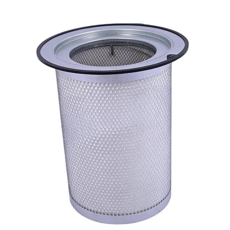
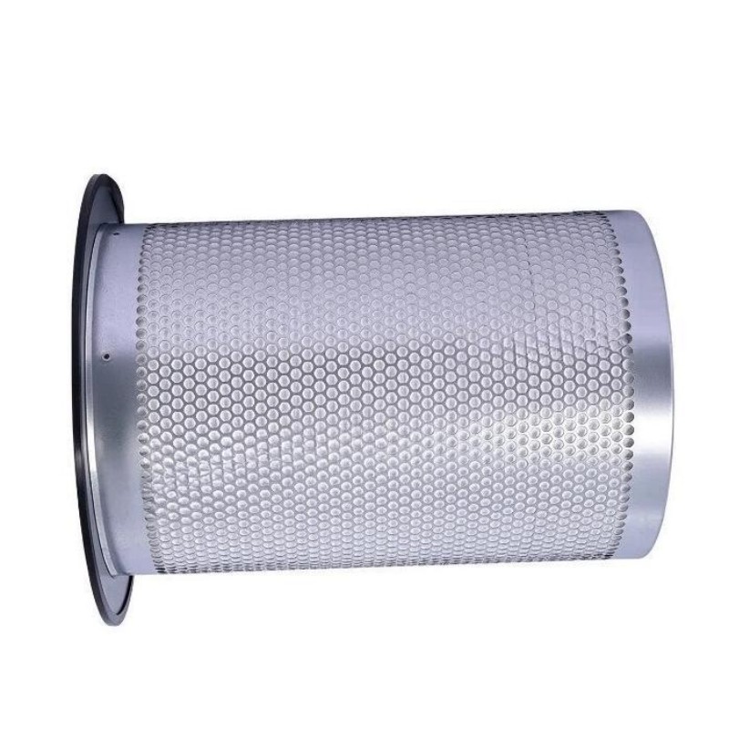
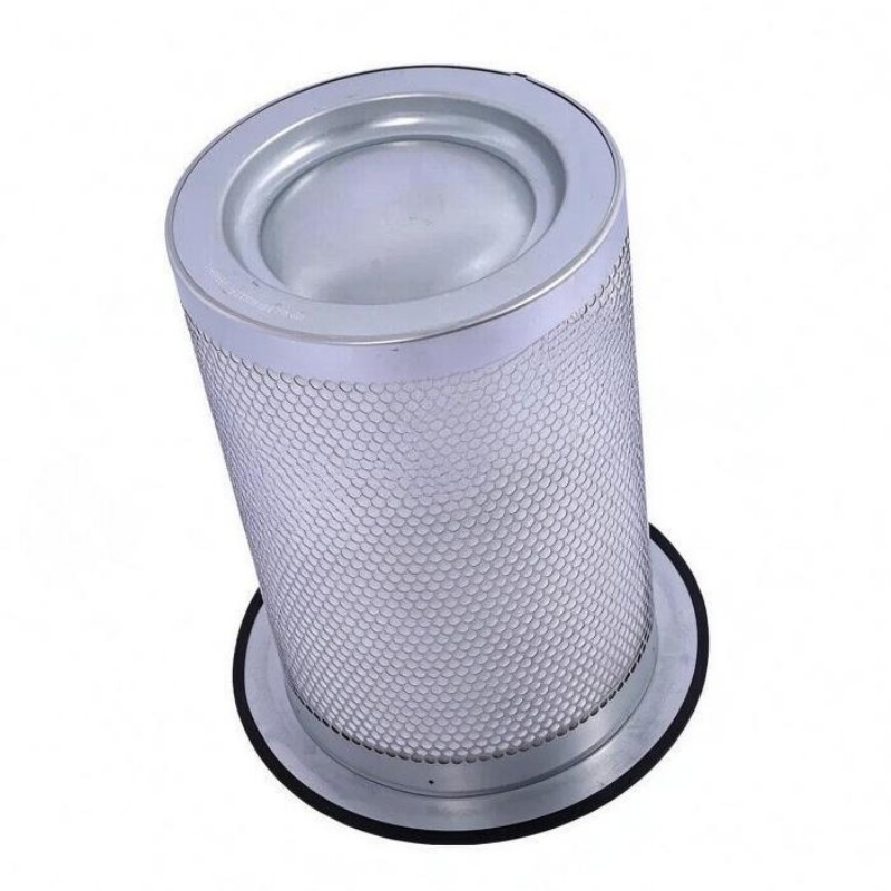
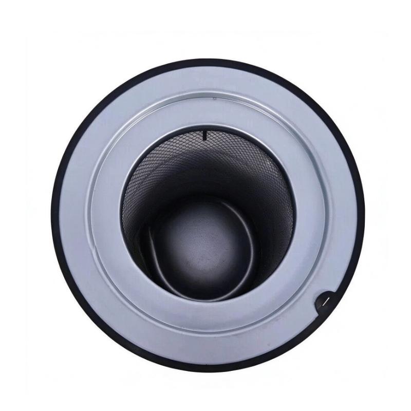
- Ingersoll Rand
- 47572176001 23545841
- Air/Oil Separator
- USA
- 375 mm
- 7.5 kg
- Xiamen, China
- New & In Stock
- T/T, PayPal, Western Union
- 1 Year
- 1-3 Working Days
- DHL, UPS, TNT, FedEx and EMS.
- 24-Hour Service
- COO
- 7
Our advantage

Global Logistics
We have a 10-year logistics and express cooperation agreement, so our products can be shipped to any place in the world.

Brand new and original
Our products are imported in bulk from the place of origin. Because of the cooperative relationship, our products are all original and 100% new.

24-hour service
We provide 7*24 hours service to our customers. We will be there whenever you need us.

Price advantage
All our products are priced very favorably because we have our own warehouse and supply.
| Company Information | |||
| [email protected] | |||
| Mobile | +8615980777398 | ||
| +8615980777398 | |||
| 15980777398 |
Product Overview
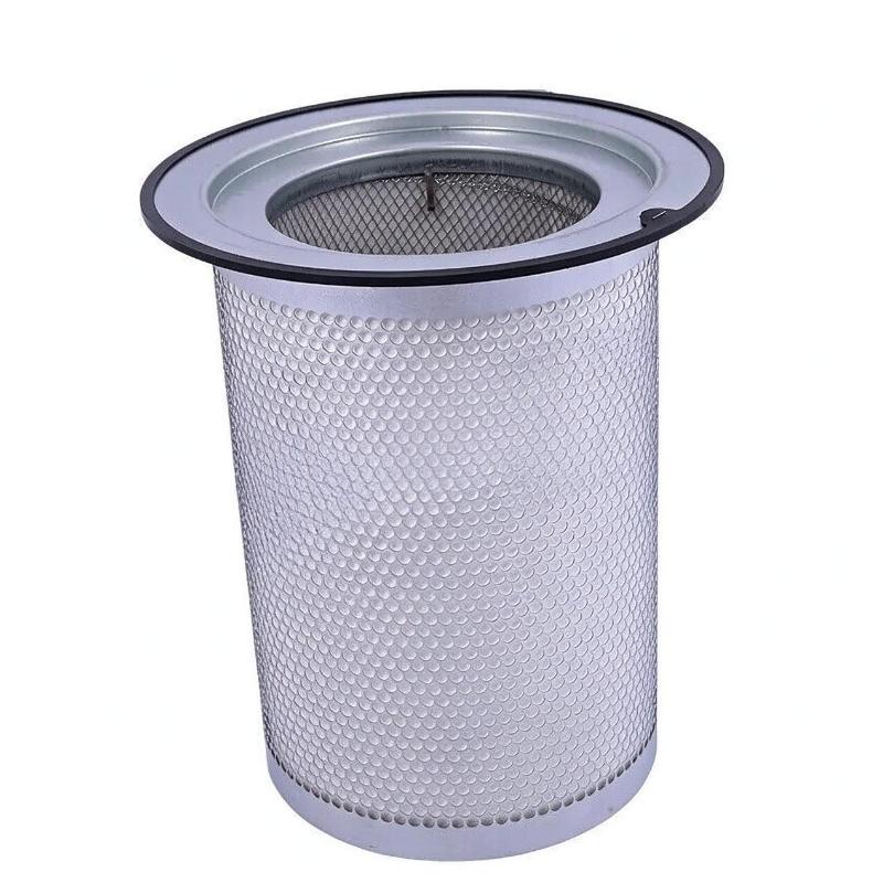
The Ingersoll Rand 47572176001 23545841 Air/Oil Separator is a replacement separation element used in compatible oil-injected rotary screw air compressors. Its primary function is to separate lubricant droplets and entrained oil mist from compressed air before the air enters the downstream delivery circuit. At the same time, the separated lubricant is returned to the compressor’s oil circulation system for continued use.
During compression, air and lubricant mix inside the compression element. The lubricant helps seal the rotor clearances, lubricate internal components, and remove heat generated during compression. Before the compressed air can be delivered to the plant’s distribution network, most of this entrained lubricant must be removed. The air/oil separator performs this function within the compressor’s separator vessel.
The 23545841 element is listed for selected Ingersoll Rand R-series compressors, including applicable R90i, R110i, R132i, and R160i configurations. Its suitability depends on the installed compressor model, production configuration, and separator assembly. The replacement element must match the required part specification and the mounting arrangement of the original equipment.
Separation performance depends on the condition of the media, the airflow through the element, the operating pressure, and the condition of the surrounding seals. As compressed air passes through the separator media, entrained oil droplets are captured and coalesce into larger droplets. The collected lubricant can then drain or return through the designated recovery arrangement, while the treated compressed air continues downstream.
The condition of the separator element has a direct effect on compressor operation. A restricted element can increase pressure drop across the separation stage, potentially increasing energy consumption. A damaged element or a compromised seal can allow excessive oil carryover into the compressed-air line, resulting in lubricant consumption, contamination of downstream equipment, and additional maintenance requirements.
Separator replacement is therefore more than a routine filter change. Maintenance personnel should inspect the separator vessel, sealing surfaces, lubricant return path, and associated components when servicing the element. If the removed separator shows unusual deposits or damage, the underlying cause should be investigated before the compressor returns to normal service.
The Ingersoll Rand 47572176001 23545841 Air/Oil Separator supports the separation and lubricant-recovery functions of compatible compressor systems. Correct selection, careful installation, and adherence to the equipment’s service requirements help maintain the intended balance between oil retention, compressed-air quality, and operating efficiency.
Technical Specifications
| Parameter | Specification |
|---|---|
| Manufacturer | Ingersoll Rand |
| Model | 47572176001 |
| Part Number | 23545841 |
| Product Type | Air/Oil Separator |
| Product Category | Compressor Separation Element |
| Equipment Type | Oil-Injected Rotary Screw Air Compressor |
| Primary Function | Separates entrained lubricant from compressed air |
| Separation Method | Coalescing filtration |
| Installation Location | Separator vessel |
| Lubricant Recovery | Through the designated compressor oil-return arrangement |
| Application | Compressed-air and lubricant separation |
| Associated Equipment Family | Ingersoll Rand R-series compressors |
| Compatible Configurations | Subject to the specific compressor parts configuration |
| Maintenance Type | Periodic inspection and separator-element replacement |
| Diameter | 375 mm |
| Weight | 7.5 kg |
Product Features
- Air/oil separation: Removes entrained lubricant from compressed air within compatible compressor systems.
- Coalescing filtration: Collects fine oil droplets and combines them into larger droplets for separation.
- Lubricant recovery support: Works with the designated oil-return arrangement to help return separated lubricant to the circulation system.
- Compressed-air quality management: Helps limit oil carryover into downstream piping and equipment.
- Pressure-drop considerations: Requires maintenance when loading or restriction begins to affect the intended airflow.
- Separator vessel integration: Depends on correct seating, sealing, and compatibility with the existing vessel assembly.
- Service replacement: Supports scheduled compressor maintenance without automatically replacing the complete separator vessel.
- Contamination control: Helps reduce lubricant carryover that can affect downstream filters, dryers, pneumatic tools, and process equipment.
Working Principle
The Ingersoll Rand 23545841 Air/Oil Separator operates through coalescing separation. In an oil-injected rotary screw compressor, compressed air leaving the compression element contains entrained lubricant in the form of droplets and fine oil mist. The separator element reduces this oil content before the compressed air proceeds to the delivery system.
Compression Element → Air/Oil Mixture → Separator Vessel and Element → Separated Compressed Air → Downstream Circuit
As the air/oil mixture enters the separator vessel, the initial flow arrangement allows part of the lubricant to separate from the air. The remaining mixture passes through the separator media, where fine oil droplets are captured. As these droplets accumulate, they combine into larger droplets that can drain through the designated collection and recovery path.
The separated lubricant is returned to the compressor’s lubrication circuit through the system’s oil-return arrangement. This helps maintain lubricant circulation while reducing the amount of oil carried out with the compressed air. The exact return mechanism depends on the compressor’s separator design.
As the element operates, its media gradually accumulates contaminants. Under unsuitable operating conditions, deposits or excessive loading can increase resistance to airflow. The resulting pressure drop can reduce separation-system efficiency and raise the energy required to deliver compressed air.
Oil carryover can also increase when the separator media is damaged, the element is incorrectly installed, or sealing surfaces do not provide the required closure. A blocked or incorrectly functioning oil-return line can interfere with lubricant recovery even when the separator media remains intact.
When replacing the element, the technician must preserve the intended airflow direction and sealing arrangement. The separator vessel should be inspected for contamination, and the oil-return passage should be checked where accessible under the prescribed maintenance procedure.
After installation, the compressor should be returned to service according to its commissioning procedure. Operating pressure, leakage, and lubricant carryover should be assessed using the equipment’s prescribed checks. Persistent oil carryover or abnormal pressure drop may require investigation of the separator element, oil-return circuit, lubricant condition, and operating conditions.
Role in the Compressor Air and Lubricant Circuit
The 23545841 Air/Oil Separator is installed within the separation stage of compatible oil-injected rotary screw compressors. It removes entrained lubricant from the compressed-air stream while allowing the recovered oil to return to the lubrication circuit.
Compression Element → Separator Vessel → Air/Oil Separator Element → Downstream Air Circuit
Separated Lubricant → Oil Recovery Path → Lubricant Circuit
| System Component | Function |
|---|---|
| Air/Oil Separator Element | Captures entrained oil droplets from compressed air |
| Separator Vessel | Receives the air/oil mixture and houses the separation assembly |
| Oil Recovery Line | Returns separated lubricant through the designated recovery path |
| Lubricant Filter | Removes particulate contaminants from circulating lubricant |
| Lubricant Cooler | Removes heat from the circulating lubricant |
| Minimum Pressure Valve | Helps maintain the required pressure conditions in applicable compressor designs |
| Compression Element | Compresses incoming air and mixes it with lubricant in oil-injected designs |
| Aftercooler | Reduces compressed-air temperature downstream where fitted |
| Moisture Separator | Removes condensed liquid from compressed air where fitted |
| Compressor Controller | Monitors available operating signals and coordinates compressor operation |
The precise arrangement depends on the compressor model and package configuration. The separator element must match the designated vessel and oil-recovery arrangement.
Industrial Applications
| Application | Typical Use |
|---|---|
| Rotary Screw Air Compressors | Separating lubricant from compressed air before delivery |
| Ingersoll Rand R-Series Equipment | Separator replacement in compatible compressor configurations |
| Automotive Manufacturing | Maintaining compressed-air quality for pneumatic production equipment |
| Metalworking Facilities | Reducing lubricant carryover into downstream air systems |
| Packaging Plants | Supporting compressed-air supply for pneumatic machinery |
| Industrial Manufacturing | Maintaining separation performance in plant air compressor systems |
| Process Industries | Limiting oil contamination in compressed-air distribution networks |
| Central Compressor Rooms | Supporting continuous compressed-air generation for multiple users |
| Compressor Overhaul | Renewing the separator element during scheduled equipment servicing |
| Preventive Maintenance Programs | Monitoring separator condition and replacing elements at prescribed intervals |
Installation and Maintenance
- Isolate the compressor: Stop the machine and follow the prescribed lockout procedure before beginning separator maintenance.
- Depressurize the system: Confirm that the separator vessel and associated piping have been safely depressurized before opening the assembly.
- Allow the equipment to cool: Ensure the vessel and lubricant have reached a safe condition for servicing.
- Identify the correct element: Confirm that part 23545841 matches the compressor’s installed separator assembly and applicable parts configuration.
- Open the separator vessel: Follow the equipment-specific procedure and avoid damaging the vessel cover, fasteners, or sealing surfaces.
- Remove the old element: Lift out the separator carefully and prevent accumulated contaminants from entering the clean-air or lubricant passages.
- Inspect the vessel: Check for residue, corrosion, damaged contact surfaces, and other conditions that could affect the new element’s installation.
- Examine the oil-return path: Inspect the designated recovery components where accessible and address blockages or damage according to the service procedure.
- Prepare the sealing surfaces: Clean the relevant contact areas and replace required seals in accordance with the applicable maintenance instructions.
- Install the replacement separator: Position the element correctly and ensure that its sealing arrangement is seated as specified.
- Restore and test the system: Reassemble the vessel, restore the compressor to service under the approved procedure, and check for leakage and abnormal operating indications.
- Record the service results: Document the replacement, operating hours, and any unusual contamination, pressure-drop indications, or oil carryover observed during maintenance.
If oil carryover remains excessive after replacement, investigate the installation, sealing arrangement, oil-return circuit, lubricant condition, and operating conditions. Replacing the element repeatedly without identifying the cause may not resolve the underlying problem.
Related Components
| Component | Function |
|---|---|
| Ingersoll Rand 23545841 Air/Oil Separator | Separates entrained lubricant from compressed air |
| Separator Vessel | Houses the separator element and supports the separation process |
| Separator Element Seals | Help prevent unfiltered flow from bypassing the element |
| Oil Recovery Line | Returns collected lubricant to the compressor lubrication circuit |
| Lubricant Filter | Removes particulate contaminants from circulating oil |
| Lubricant Cooler | Helps control lubricant temperature |
| Minimum Pressure Check Valve | Supports pressure regulation and check-valve operation in the applicable system |
| Air Filter Element | Removes airborne particles before air enters the compression element |
| Pre-Filter Pad | Provides preliminary filtration upstream of the main intake filter |
| Aftercooler | Reduces compressed-air temperature downstream where fitted |
Recommended Related Models
| Model | Product Type | Typical Application |
|---|---|---|
| Ingersoll Rand 23545841 | Air/Oil Separator | Separation-element replacement in compatible R-series compressor configurations |
| Ingersoll Rand 23566938 | Air/Oil Separator | Related separator reference listed for selected R132 compressor configurations |
| Ingersoll Rand 54509427 | Air/Oil Separator | Alternative separator reference for designated R132 configurations |
| Ingersoll Rand 23487457 | Air Filter | Intake-air filtration in compatible compressor systems |
| Ingersoll Rand 23424922 | Coolant Filter | Lubricant filtration in compatible compressor configurations |
| Ingersoll Rand 23523772 | Filter Pad | Preliminary intake filtration in designated compressor assemblies |
Key Advantages
- Helps reduce lubricant carryover into the compressed-air delivery circuit.
- Supports lubricant recovery within compatible oil-injected compressor systems.
- Helps maintain separation performance when correctly installed and maintained.
- Supports compressed-air quality management for downstream equipment.
- Provides a service replacement option for compatible separator vessels.
- Helps maintenance teams identify oil-return, sealing, and contamination issues during servicing.
Technical FAQs
What is the difference between an air/oil separator and a coolant filter?
The air/oil separator removes entrained lubricant from compressed air after the compression process. A coolant filter, by contrast, filters particulate contaminants from the circulating lubricant. Both components support the compressor’s fluid-management system, but they perform different functions and are not interchangeable.
How can a restricted separator element affect compressor operation?
A restricted element can increase pressure drop across the separation stage, which may raise energy consumption and affect operating performance. The extent of the effect depends on the compressor design and operating conditions, so pressure-drop indications should be assessed against the equipment’s maintenance requirements.
What can cause oil carryover after the separator has been replaced?
Possible causes include incorrect element seating, damaged seals, an obstructed oil-return path, unsuitable lubricant conditions, or operating conditions outside the intended range. The entire separation arrangement should be inspected before assuming that the replacement element is defective.
Why must the separator element match the installed compressor configuration?
Separator elements can differ in their construction, mounting interfaces, sealing arrangements, and separation characteristics. A physically similar element may not provide the required fit or performance. The part reference should therefore be matched to the compressor’s applicable parts information.