
NewsNEWCENTER
Featured products
Contact Us
Allen-Bradley 1606-XLS480E-3 Troubleshooting Guide: Power Supply Fault Diagnosis, Testing, and Maintenance
2026-10-19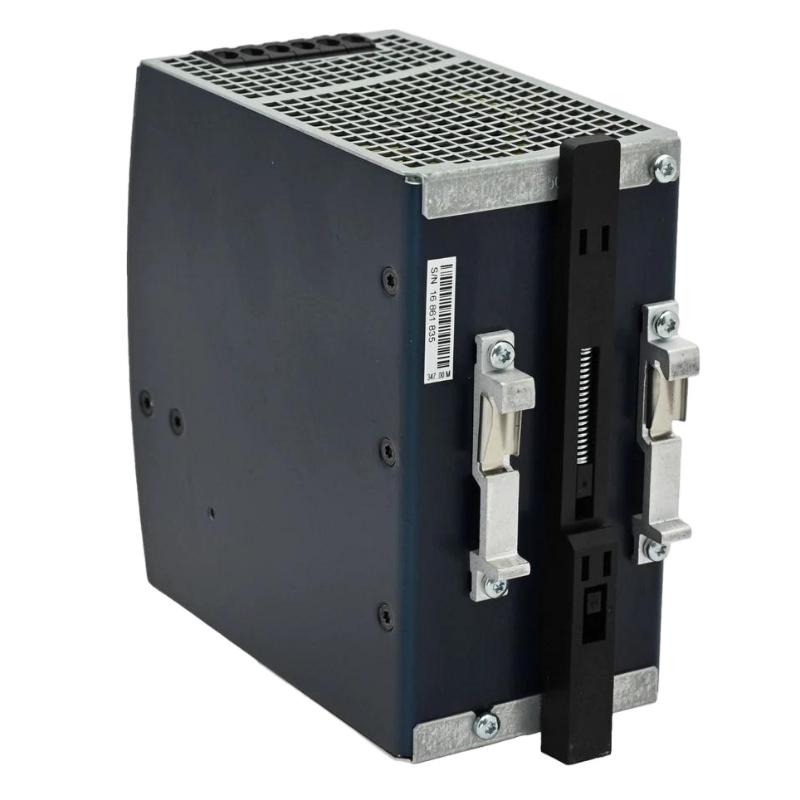
1. Product Overview
The Allen-Bradley 1606-XLS480E-3 is a 480 W industrial switching power supply designed to deliver regulated 24V DC power to automation and control equipment. It belongs to the Allen-Bradley 1606 XLS Performance family and provides a rated output of 20 A at 24V DC, with an adjustable output range of 24–28V DC. The unit is designed for three-phase 380–480V AC input and supports a specified high-voltage DC input range. Its DC OK relay contact enables external monitoring of power supply status, helping control systems identify certain output-related conditions. When the 1606-XLS480E-3 fails to operate correctly, common symptoms include no DC output, low output voltage, intermittent power interruptions, an unexpected DC OK status, or shutdown under load. These symptoms can result from upstream power problems, overloaded output circuits, wiring defects, unsuitable operating conditions, or an internal power supply fault. A systematic troubleshooting procedure helps isolate the cause before replacing the unit or disturbing connected automation equipment.
2. Safety Precautions
The 1606-XLS480E-3 uses hazardous three-phase AC or high-voltage DC input. Only qualified personnel should carry out electrical testing and maintenance. Before troubleshooting:
- Follow the site’s lockout/tagout procedures.
- Isolate all relevant input sources and verify the absence of hazardous voltage.
- Use appropriately rated test instruments and protective equipment.
- Follow the manufacturer’s discharge and waiting instructions.
- Prevent accidental contact between conductors and exposed terminals.
- Keep PLC and process equipment in an approved maintenance state.
Do not disconnect live input conductors, bypass protective devices, or open the power supply enclosure for unauthorized component-level repair. If there is evidence of burning, arcing, smoke, or severe overheating, isolate the unit and arrange qualified evaluation.
3. Common Symptoms and Possible Causes
| Symptom | Possible Causes | Initial Check |
|---|---|---|
| No DC output | Missing input power, incorrect input connection, output short circuit, or internal fault | Verify the input supply and inspect external wiring after isolation |
| Output voltage is too low | Excessive load, voltage drop, loose connections, or incorrect adjustment | Measure output voltage and review the total load current |
| Output drops when equipment starts | High startup current, overloaded supply, or excessive cable resistance | Check peak demand and output wiring |
| DC OK signal indicates a fault | Output condition outside the normal status criteria, wiring error, or PLC input issue | Measure output voltage and verify the relay-contact circuit |
| Intermittent power interruptions | Unstable input, loose connections, excessive temperature, or intermittent overload | Review input stability, load behavior, and cabinet ventilation |
| Unit operates unusually hot | High load, inadequate ventilation, elevated ambient temperature, or internal damage | Check load demand and airflow; isolate if overheating is severe |
| Repeated protective shutdown | Output short circuit, overload, wiring defect, or internal failure | Inspect downstream circuits and verify load requirements |
These symptoms are diagnostic starting points, not proof of a specific internal failure. Confirm the actual operating conditions before deciding whether the power supply needs replacement.
4. Troubleshooting a No-Output Condition
4.1 Verify the Incoming Supply
Start by confirming that the upstream supply matches the 1606-XLS480E-3 input requirements. For AC operation, verify the three-phase supply and its voltage against the specified 380–480V AC range. Do not assume that a power supply is defective simply because the output is absent. An upstream protective device may have tripped, a phase may be missing, or the incoming voltage may be outside the permitted range. Input testing involves hazardous voltages and must be performed by qualified personnel using appropriate procedures and instruments. If the input source is abnormal, correct the upstream problem before proceeding.
4.2 Inspect External Connections
After isolating the equipment, inspect the input terminals, protective-earth connection, output conductors, and downstream distribution terminals. Look for loose connections, damaged insulation, corrosion, discoloration, or evidence of overheating. Confirm that the input conductors are connected to the correct terminals and that the DC output polarity is correct. Do not infer terminal assignments from another model in the 1606 family. Use the diagram for the exact 1606-XLS480E-3.
4.3 Check for an Output Short Circuit
A short circuit or damaged downstream cable can prevent the supply from operating normally or cause protective behavior. With the system safely isolated, inspect the output wiring and downstream branches. If the approved troubleshooting procedure permits, isolate individual load branches to identify whether a particular circuit is responsible. Do not disconnect critical loads without authorization. If the supply returns to normal after an external circuit fault is corrected, verify the complete system under controlled conditions before restoring normal operation.
5. Diagnosing Low Output Voltage
5.1 Measure Voltage at the Power Supply
Measure the DC output using an appropriately rated instrument. Compare the result with the expected operating voltage and the selected adjustment setting. The output is adjustable from 24V to 28V DC. The nominal value for a typical 24V control system is 24V DC, but the actual acceptance range should be determined from the connected equipment and the system design. If the measured voltage is abnormal, check the load and wiring before assuming that the internal regulation circuit has failed.
5.2 Check the Total Load Current
The rated continuous output is 20 A at 24V DC, corresponding to 480 W. Calculate the current drawn by all connected loads, including PLC modules, relays, communication devices, sensors, and actuators. A load that approaches or exceeds the rated capacity may cause voltage instability or protective behavior, particularly when several devices start simultaneously. The power supply supports temporary reserve current under specified conditions, but this capability is not a substitute for adequate continuous capacity. If the load regularly exceeds 20 A at 24V DC, reassess the power-distribution design.
5.3 Inspect DC Distribution Wiring
A voltage measurement taken at the power supply may differ from the voltage at a remote PLC or field device. Long cables, undersized conductors, loose terminals, and poor connections can create voltage drops under load. Measure the voltage at the affected equipment using an approved procedure. If the supply output is correct but the device voltage is low, investigate the distribution conductors, terminal blocks, protective devices, and branch loading. Do not increase the output voltage beyond the connected equipment’s permitted range to compensate for poor wiring.
6. Troubleshooting Intermittent Shutdowns
6.1 Review Input Power Stability
Intermittent loss of output may originate from an unstable upstream supply or an input connection problem. Review the incoming voltage and any upstream protective-device events. If interruptions occur when large equipment starts, investigate supply disturbances and input wiring. Confirm that the installation follows the required electrical protection and conductor-sizing practices.
6.2 Check Temperature and Ventilation
The 1606-XLS480E-3 requires suitable airflow and environmental conditions. Blocked ventilation, high cabinet temperature, or adjacent heat-generating equipment may affect reliable operation. Inspect the cabinet for dust accumulation, restricted airflow, and excessive ambient temperature. The unit’s published operating range and derating requirements should be checked before assuming that full output capacity is available at elevated temperatures. If the unit is severely overheated, isolate it safely and investigate the cause before returning it to service.
6.3 Investigate Load Transients
Some loads draw substantially more current during startup than during steady-state operation. Motors, capacitive loads, relays, and groups of simultaneously energized devices may create transient demands that disturb the DC bus. Review load startup sequences and measure the current where suitable equipment is available. Consider staggering startup events or redistributing loads if the system design permits. Do not rely on the short-duration reserve-current rating as a guarantee that every startup transient can be supported.
7. Troubleshooting the DC OK Relay Signal
The DC OK relay contact allows the power supply’s status to be monitored by a PLC, alarm circuit, or other compatible control input. If the signal does not match the expected state, investigate both the power supply and the external monitoring circuit.
7.1 Verify the Actual Output Voltage
First measure the DC output directly. If the output is outside the expected operating condition, investigate the input supply, load current, wiring, and power supply status before focusing on the relay circuit. If the output voltage is normal but the PLC reports an alarm, the issue may be in the contact wiring, input configuration, or control logic.
7.2 Check Relay Wiring and PLC Logic
With the circuit safely isolated, verify the contact terminals against the manufacturer’s wiring diagram. Confirm that the PLC program uses the intended contact behavior and that the input is configured correctly. Do not assume that a particular contact is normally open or normally closed without checking the documentation. Avoid modifying alarm logic simply to suppress a warning.
7.3 Confirm the Alarm Response
After correcting the fault, test the monitoring circuit using an approved commissioning procedure. Confirm that the PLC or alarm system detects the expected status changes and that the response is appropriate for the process. The DC OK contact is a monitoring feature; it does not replace independent overcurrent protection or process safety functions.
8. Troubleshooting Excessive Heat or Abnormal Noise
8.1 Check Load and Environmental Conditions
A power supply operating under heavy load generates heat. Verify that the continuous load remains within the rated capacity and that the installation meets the manufacturer’s ventilation and temperature requirements. Check for dust, restricted airflow, and nearby heat sources. Do not cover the unit or place other equipment where it obstructs the required cooling path.
8.2 Identify Signs of Internal Damage
Unusual noise accompanied by burning odors, visible damage, repeated shutdowns, or abnormal heating may indicate a serious fault. Isolate the unit and do not continue operating it merely to gather additional symptoms. Do not open the enclosure or attempt to replace internal components without the required authorization and service capability. Arrange qualified evaluation or replace the unit according to the site’s maintenance procedure.
9. Repair and Replacement Procedure
The 1606-XLS480E-3 is a high-voltage-input industrial power supply. Troubleshooting should focus first on the external input supply, protective devices, wiring, DC load, ventilation, and monitoring circuit. A practical maintenance sequence is:
- Document the symptom and operating conditions.
- Isolate the equipment and apply lockout/tagout.
- Verify the input supply and external protective devices.
- Inspect input, output, and protective-earth wiring.
- Check the load current and downstream circuits.
- Measure the DC output using an approved procedure.
- Verify the DC OK relay circuit where applicable.
- Determine whether the fault remains after external problems are corrected.
- Arrange qualified evaluation or replacement if an internal fault is suspected.
- Perform controlled commissioning tests before returning the system to service.
Do not attempt component-level repair on the internal switching electronics without the appropriate technical resources. If replacement is necessary, verify the input range, output voltage, current capacity, physical mounting, terminal arrangement, and monitoring requirements of the proposed replacement.
10. Preventive Maintenance Checklist
Regular maintenance helps reduce unexpected shutdowns and improve the reliability of the 24V DC distribution system.
- Inspect the enclosure and surrounding cabinet for contamination or damage.
- Confirm that ventilation paths are unobstructed.
- Check input and output connections according to the maintenance procedure.
- Verify the DC output under representative operating loads.
- Review DC OK alarms and recurring supply interruptions.
- Recalculate the load after new devices are added.
- Inspect protective devices and grounding arrangements.
- Document abnormal measurements and corrective actions.
Avoid unnecessary live testing or repeated power cycling. Any electrical inspection should be performed by qualified personnel using the appropriate safety procedures.
11. Frequently Asked Questions
Why does the Allen-Bradley 1606-XLS480E-3 have no output?
Possible causes include missing three-phase input power, an upstream protective device that has tripped, incorrect wiring, an output short circuit, or an internal fault. Verify the input and external circuits before concluding that the unit has failed.
Why does the output voltage drop when the PLC system starts?
Possible causes include high startup current, excessive total load, poor connections, or voltage drop in the DC distribution wiring. Check transient demand and measure the voltage at both the power supply and the affected load.
Can the output be adjusted to compensate for voltage drop?
The output can be adjusted within its specified 24–28V DC range, but any setting must remain compatible with the connected equipment. Correct undersized conductors, loose connections, or excessive loading rather than using an excessive voltage setting as a workaround.
What does the DC OK relay do?
It provides a status contact for external monitoring. If its signal appears incorrect, verify the actual DC output, relay wiring, and PLC input logic.
When should the power supply be replaced?
Consider replacement when the unit continues to malfunction after the input supply, external wiring, load demand, and operating environment have been verified. Internal damage should be evaluated by qualified personnel.
12. Technical Summary
The Allen-Bradley 1606-XLS480E-3 is a 480 W industrial power supply with a nominal 24V DC output, a 20 A continuous rating, and a three-phase 380–480V AC input option. Its DC OK relay provides an additional means of monitoring power supply status. Effective troubleshooting starts with the incoming supply, external protection, DC load, output wiring, temperature, and status-monitoring circuit. By checking these factors systematically and following appropriate high-voltage safety procedures, maintenance personnel can distinguish external installation problems from a potential internal power supply failure and reduce unnecessary downtime.