
NewsNEWCENTER
Featured products
Contact Us
Allen-Bradley 1606-XLS480E-3 Power Supply Installation Guide: Wiring, Setup, and Commissioning
2026-10-19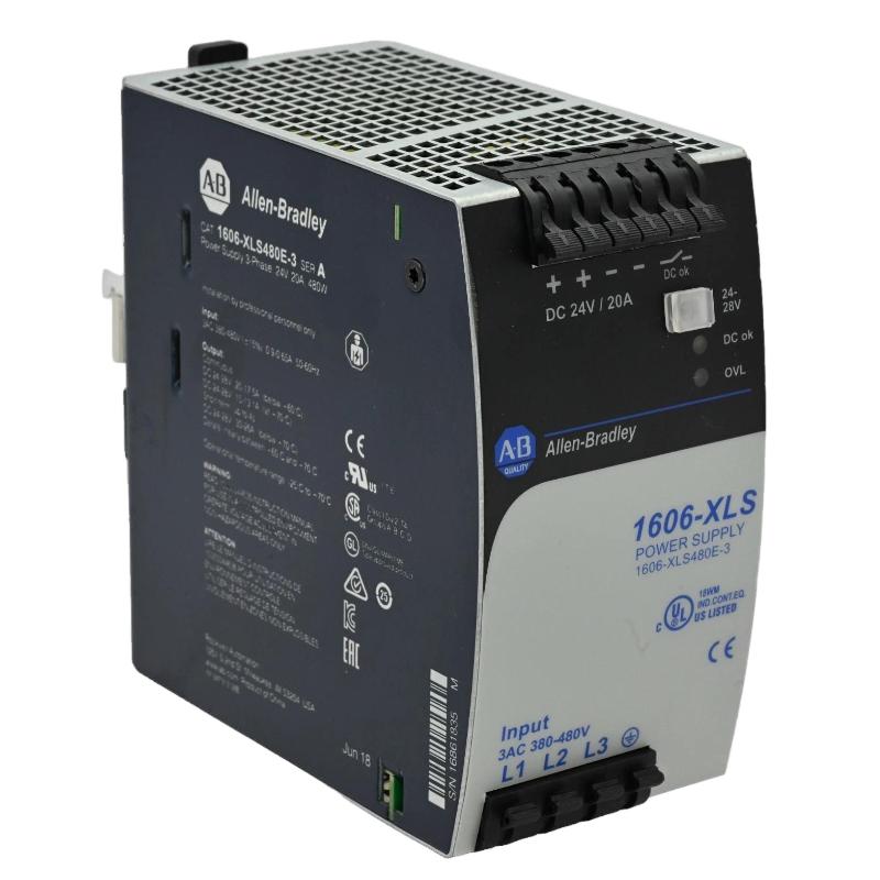
1. Product Overview
The Allen-Bradley 1606-XLS480E-3 power supply is a high-performance industrial switching power supply designed to deliver regulated 24V DC power to automation and control equipment. Part of the Allen-Bradley 1606 XLS Performance family, this model provides a rated output of 480 W and 20 A at 24V DC, making it suitable for industrial control cabinets, PLC systems, distributed control equipment, sensors, relays, and other DC-powered devices. A key characteristic of the 1606-XLS480E-3 is its three-phase AC input design. It accepts a nominal input range of 380–480V AC and can also operate from a specified high-voltage DC input range. This distinguishes it from similar 1606-XLS480E models designed for different input supplies. Selecting the correct version is essential for safe installation and reliable operation. The power supply provides an adjustable DC output within its specified range of 24–28V DC. It also features a DC OK relay contact for monitoring the output status and supports temporary reserve output current for short-duration load peaks under specified conditions. Proper installation involves checking the incoming power system, selecting appropriate upstream protection, confirming the DC load requirements, mounting the unit securely, and testing the output before connecting critical automation equipment.
2. Technical Specifications
| Parameter | Specification |
|---|---|
| Manufacturer | Allen-Bradley / Rockwell Automation |
| Model | 1606-XLS480E-3 |
| Product type | Industrial switching power supply |
| Product family | 1606 XLS Performance |
| Nominal output voltage | 24V DC |
| Adjustable output voltage | 24–28V DC |
| Rated output current | 20 A at 24V DC |
| Rated output power | 480 W |
| AC input | Three-phase, 380–480V AC, 47–63 Hz |
| DC input operating range | 450–780V DC |
| Typical efficiency | Approximately 95% |
| Typical hold-up time | 19 ms |
| Typical reserve output current | 30 A at 24V DC for approximately 4 seconds under specified conditions |
| Mounting | DIN-rail mounting |
| Connection terminals | Spring-clamp terminals |
| Degree of protection | IP20 |
| Dimensions | Approximately 65 × 124 × 127 mm (W × H × D) |
| Weight | Approximately 0.87 kg |
These specifications describe the standard 1606-XLS480E-3 version. Verify the nameplate, applicable installation instructions, and site electrical requirements before selecting protective devices or connecting the supply.
3. Installation Preparation
3.1 Verify the Input Power System
Before installing the Allen-Bradley 1606-XLS480E-3, confirm that the incoming supply matches the three-phase input requirements. Do not connect a single-phase supply or a lower-voltage source merely because a similar power supply in the 1606 family accepts it. Check the following:
- Confirm the catalog number on the product label.
- Verify the nominal three-phase AC supply voltage and frequency.
- Confirm the supply’s protective earthing arrangement.
- Review the required upstream circuit protection.
- Verify the DC load’s voltage, steady-state current, and startup demand.
- Check that the control cabinet provides adequate ventilation.
- Confirm the installation complies with local electrical regulations.
The DC input option is a high-voltage input and must not be confused with the 24V DC output. Only qualified personnel should design or work on this input circuit.
3.2 Calculate the DC Load
The rated output is 480 W, corresponding to 20 A at 24V DC. Calculate the total current required by all connected devices, including PLC modules, communication equipment, relays, sensors, and actuators. For a basic load calculation:
Total Load Current = Sum of Individual Device Currents

Total Load Power = Output Voltage × Total Load Current
Allow for startup surges and transient loads. The temporary reserve-current capability should not be treated as a continuous operating rating. If the load regularly exceeds the rated current, select an appropriately sized power supply or redesign the load distribution.
3.3 Prepare the Mounting Location
Mount the unit on a suitable DIN rail inside an industrial control cabinet. Maintain the clearances specified by the manufacturer to allow heat to dissipate and to provide access for wiring and maintenance. Avoid placing the power supply directly beside high-heat components unless the cabinet’s thermal design accounts for the additional temperature. Dust, moisture, conductive contamination, and restricted airflow can reduce service life and reliability.
4. Safety Requirements Before Wiring
The 1606-XLS480E-3 operates with hazardous three-phase AC input or a high-voltage DC input. Installation must be carried out by qualified electrical personnel. Before wiring:
- Isolate all relevant power sources.
- Apply lockout/tagout procedures.
- Verify the absence of hazardous voltage with an appropriate instrument.
- Confirm that protective earthing is available and correctly installed.
- Follow the manufacturer’s terminal diagram and tightening requirements.
- Keep the input and output circuits clearly identified.
Never connect or disconnect input conductors while energized. Do not use the 24V output terminals as a test point for the incoming supply, and do not assume that disconnecting the AC source immediately removes all stored electrical energy.
5. Input and Output Wiring
5.1 Connect the Three-Phase Input
Identify the input terminals using the diagram supplied for the exact unit. Connect the three-phase conductors according to the marked terminals and the manufacturer’s instructions. Verify that the supply voltage falls within the specified range before energizing the unit. Select upstream protective devices and conductors according to the installation manual, available fault current, wiring method, ambient temperature, and applicable electrical code. The appropriate fuse or circuit breaker must not be selected solely from the nominal output current.
5.2 Connect Protective Earth
Connect the protective earth conductor to the designated protective-earth terminal. Confirm the integrity of the earth connection and follow the grounding requirements for the control cabinet. Protective earthing is an essential safety measure. It must not be replaced by a DC negative connection or an improvised grounding arrangement.
5.3 Connect the 24V DC Output
Connect the positive and negative output conductors to the designated DC output terminals. Confirm polarity before connecting the load. Use conductors and distribution protection appropriate for the expected current. A simplified functional arrangement is shown below:
Three-Phase AC Supply
          |
          v
Allen-Bradley 1606-XLS480E-3
          |
          +---- +24V DC ---- PLC and Control Loads
          |
          +---- 0V DC ------ DC Return
          |
          +---- DC OK Relay Contact
This is an illustrative functional diagram, not a terminal-level wiring schematic. Use the product’s official terminal diagram to determine exact connections.
5.4 Connect the DC OK Relay
The power supply provides a DC OK relay contact that can be incorporated into the control system for output-status monitoring. The contact may be connected to a PLC digital input or an alarm circuit, provided the contact ratings and receiving-circuit requirements are compatible. Use the manufacturer’s diagram to identify the contact terminals and their normal operating behavior. Configure the PLC logic so that loss of the DC OK signal produces an appropriate alarm or diagnostic response.
6. Output Voltage Adjustment
The 1606-XLS480E-3 provides an adjustable output range of 24–28V DC. The nominal system voltage is normally 24V DC, and any adjustment should be based on the requirements of the connected equipment. Before changing the setting:
- Check the permitted supply-voltage range of every connected device.
- Consider voltage drop in long DC distribution cables.
- Confirm that the adjustment will not exceed the rating of any load.
- Follow the manufacturer’s procedure for adjustment and measurement.
Do not increase the output voltage simply to compensate for undersized conductors, poor connections, or an overloaded circuit. Correct the underlying distribution problem instead.
7. Commissioning Procedure
7.1 Pre-Energization Inspection
Before applying power, confirm that the input and output wiring is complete and correctly identified. Check protective earthing, upstream protection, DC polarity, terminal security, and the total expected load. Ensure that the output is not short-circuited and that all connected equipment is suitable for the selected DC voltage.
7.2 Energize the Power Supply
Restore the input supply using the approved commissioning procedure. Observe the unit’s status indications and verify that the output voltage rises to the expected level. Measure the DC output with a suitable instrument. Confirm polarity and ensure that the voltage remains within the expected range. If the unit does not start or the output is unstable, isolate the supply and investigate before proceeding.
7.3 Test Under Load
Connect or enable the intended loads according to the commissioning plan. Measure the output voltage under representative operating conditions and check for excessive voltage drop, unexpected shutdowns, or overheating. Where practical, verify the output first with a controlled load before connecting critical PLCs or process equipment. Confirm that startup current remains within the power supply’s permitted operating limits.
7.4 Verify DC OK Monitoring
Check that the DC OK relay contact changes state as expected when the power supply is operating normally. Verify that the PLC or alarm circuit receives the correct status. If the signal is incorrect, check the relay-contact wiring, PLC input configuration, and the status definitions in the product documentation.
7.5 Record Commissioning Results
Record the input voltage, output voltage, load current, status-contact behavior, and any configuration changes. Include the catalog number and installation date in the maintenance record. These measurements provide a baseline for future troubleshooting and help identify gradual changes in power quality or load demand.
8. Integration with Industrial Automation Systems
The Allen-Bradley 1606-XLS480E-3 can provide the 24V DC supply for PLC racks, control relays, sensors, industrial communication equipment, and other compatible devices. When integrating the power supply into an automation cabinet, separate critical control loads from nonessential loads where appropriate. This simplifies load calculations and can help prevent a fault in one branch from affecting the entire control system. The DC OK relay can support monitoring and alarm functions. However, the power supply’s status contact does not replace independent protection, process interlocks, or appropriate monitoring of downstream circuits.
9. Preventive Maintenance
Periodic maintenance helps maintain reliable power delivery and reduce unexpected downtime.
- Inspect the unit and surrounding cabinet for dust, moisture, or damage.
- Check that ventilation paths remain clear.
- Inspect input and output wiring for discoloration or loose connections.
- Verify the protective-earth connection according to site procedures.
- Measure the output voltage under representative load conditions.
- Review DC OK alarms and any recurring power interruptions.
- Reassess load demand after major equipment additions.
Before performing maintenance, isolate the input supply and follow the manufacturer’s safety procedure. Do not open the power supply enclosure or attempt component-level repair unless specifically authorized and equipped for that work.
10. Frequently Asked Questions
What is the rated output of the 1606-XLS480E-3?
The unit provides a nominal 24V DC output, rated at 20 A and 480 W. Its output voltage is adjustable within the specified 24–28V DC range.
What input voltage does this model require?
The 1606-XLS480E-3 is designed for three-phase 380–480V AC input at 47–63 Hz. It also supports a specified high-voltage DC input range. Always verify the exact input requirements on the unit and in its installation documentation.
Can the output voltage be adjusted to 28V DC?
The specified adjustment range is 24–28V DC, but the selected setting must remain compatible with every connected device. Check equipment ratings before making any adjustment.
What is the DC OK relay used for?
The relay contact provides a status signal that can be monitored by a PLC or alarm circuit. Its wiring and logic should follow the product documentation and the receiving circuit’s electrical requirements.
Can the power supply deliver more than 20 A?
The product supports temporary reserve output current under specified conditions, but the rated continuous output is 20 A at 24V DC. Do not use the short-duration reserve rating as a continuous load rating.
11. Technical Summary
The Allen-Bradley 1606-XLS480E-3 is a 480 W, 24V DC industrial power supply designed for three-phase 380–480V AC input or a specified high-voltage DC input. Its 20 A rated output, adjustable voltage, and DC OK relay make it suitable for a range of industrial automation power-distribution applications. Reliable installation depends on correct input selection, protective earthing, suitable circuit protection, accurate DC load calculations, and controlled commissioning. Verify all terminal assignments and installation requirements against the exact product documentation before energizing the system.
::::::writing{variant=”document” id=”85316″ title=”Allen-Bradley 1606-XLS480E-3 Power Supply Troubleshooting Guide”}