

ProductPRODUCT
Featured products
Contact Us
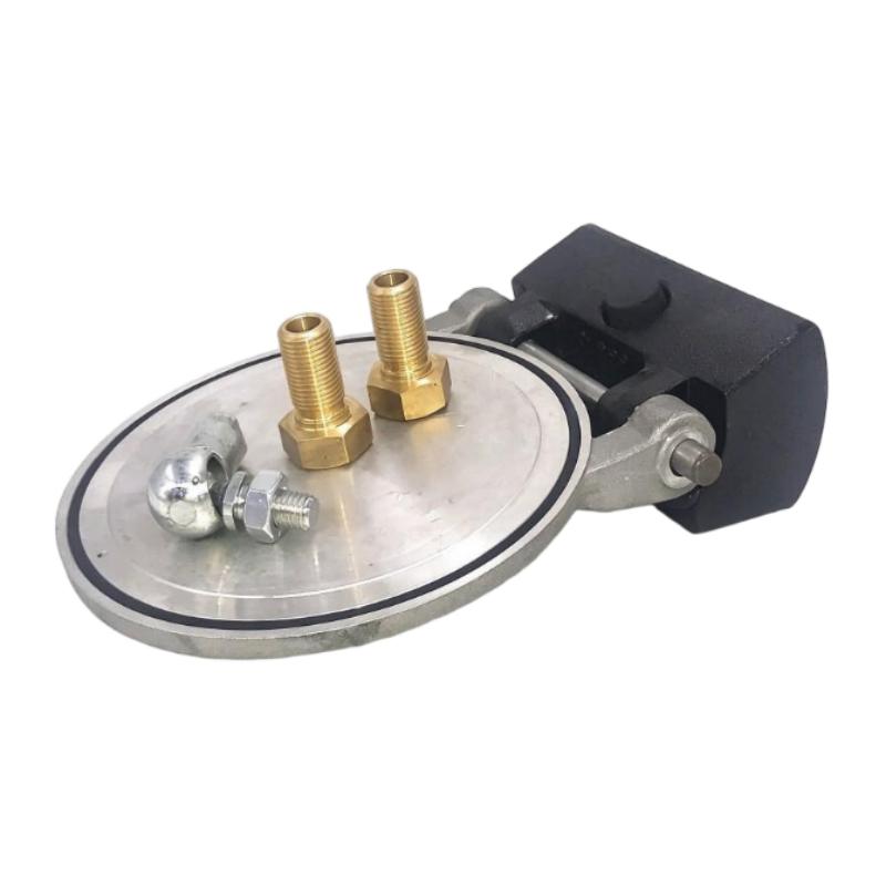
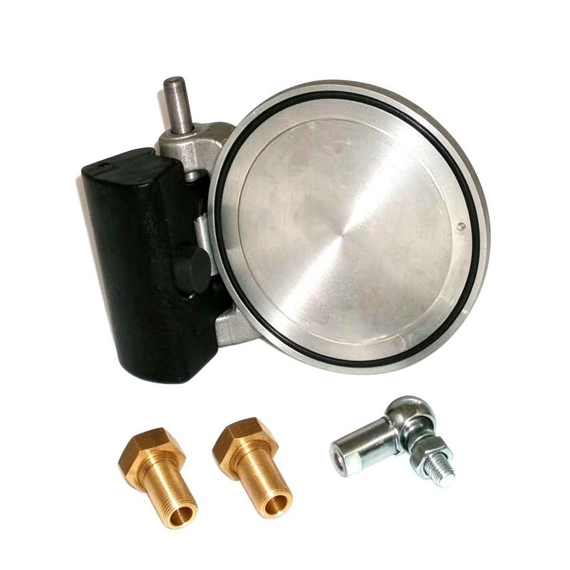
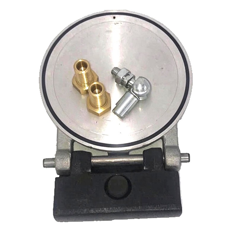
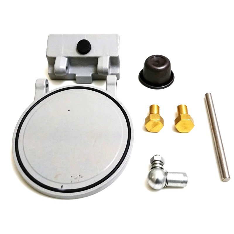
- Ingersoll Rand
- 47572168001 23531593
- Intake Valve Kit
- USA
- 300 × 250 × 200 mm
- 3.0 kg
- Xiamen, China
- New & In Stock
- T/T, PayPal, Western Union
- 1 Year
- 1-3 Working Days
- DHL, UPS, TNT, FedEx and EMS.
- 24-Hour Service
- COO
- 6
Our advantage

Global Logistics
We have a 10-year logistics and express cooperation agreement, so our products can be shipped to any place in the world.

Brand new and original
Our products are imported in bulk from the place of origin. Because of the cooperative relationship, our products are all original and 100% new.

24-hour service
We provide 7*24 hours service to our customers. We will be there whenever you need us.

Price advantage
All our products are priced very favorably because we have our own warehouse and supply.
| Company Information | |||
| [email protected] | |||
| Mobile | +8615980777398 | ||
| +8615980777398 | |||
| 15980777398 |
1. Product Overview
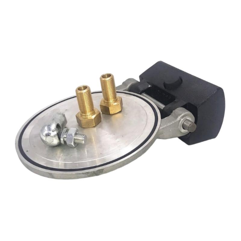
The Ingersoll Rand 47572168001 / 23531593 Intake Valve Kit is an industrial compressor-related replacement kit intended for intake valve maintenance and servicing, subject to confirmation of the exact equipment application. Intake valve assemblies play an important role in regulating the entry of air into compressor systems and supporting the intended operating cycle.
In industrial compressed-air applications, the intake valve helps manage airflow into the compression mechanism. Its condition can influence compressor starting behavior, airflow regulation, operating stability, and overall equipment performance. Worn, damaged, or incorrectly installed valve components may contribute to abnormal noise, reduced output, unstable operation, or other performance issues.
A suitable intake valve kit can help maintenance teams restore the relevant valve assembly when the original components require servicing or replacement. Before purchasing or installing the Ingersoll Rand 47572168001 / 23531593, technicians should confirm the complete part number, compressor model, valve configuration, and applicable service requirements.
With supplied dimensions of 300 × 250 × 200 mm and a listed weight of 3.0 kg, this kit can be identified and evaluated for spare-parts storage, maintenance planning, and equipment servicing. These physical specifications should be checked against the product packaging and identification label before final procurement.
2. Technical Specifications
| Parameter | Specification |
|---|---|
| Brand | Ingersoll Rand |
| Part Number | 47572168001 |
| Additional Part Number | 23531593 |
| Product Type | Intake Valve Kit |
| Product Category | Compressor Replacement and Maintenance Parts |
| Dimensions | 300 × 250 × 200 mm |
| Weight | 3.0 kg |
| Primary Function | Intake valve servicing or replacement, subject to equipment compatibility |
| Application | Industrial compressor maintenance |
| Installation Method | Follow the equipment-specific service instructions |
| Compatible Equipment | Confirm the compressor model and approved parts documentation |
| Maintenance Requirements | Inspect and service according to the manufacturer’s recommended procedures |
Important: The supplied product identifiers, dimensions, and weight are presented as provided. The exact compressor models supported, internal kit contents, sealing materials, operating limits, and installation requirements should be verified before ordering or installation.
3. Function and Working Principle
An intake valve controls or regulates the entry of air into a compressor’s compression system. The precise operating mechanism depends on the compressor design and valve assembly.
In a typical compressor arrangement, air enters through an intake path before moving into the compression mechanism. The intake valve works with the compressor’s control system and mechanical components to support the required airflow conditions. Depending on the design, the valve assembly may also participate in regulating capacity or controlling airflow during different operating states.
The Ingersoll Rand 47572168001 / 23531593 Intake Valve Kit is intended for maintenance involving the relevant intake valve assembly. Its exact internal components and operating mechanism must be confirmed from the kit documentation and the compressor model it serves.
3.1 Air Intake Regulation
The intake valve helps manage the flow of air entering the compressor. Correct valve operation supports the intended relationship between incoming air and the compressor’s operating requirements.
If the valve does not operate correctly, airflow may become restricted or fail to follow the expected control sequence. The resulting symptoms depend on the compressor architecture and the nature of the fault.
3.2 Compressor Operating Stability
An intake valve must operate consistently within its designed conditions. Wear, contamination, damaged sealing surfaces, or incorrect assembly may interfere with normal operation.
Servicing the valve with the correct replacement components can help restore the intended function when the underlying fault is associated with the valve assembly.
3.3 Relationship with the Compressor Control System
Some compressor intake assemblies operate in coordination with pneumatic, mechanical, or electronic control components. A fault affecting one part of the assembly may influence the behavior of other components.
For this reason, technicians should inspect the overall intake system and associated controls rather than assuming that every airflow-related problem originates in the valve itself.
4. Role in Industrial Compressor Systems
The intake valve is one of the components that contribute to reliable compressor operation. Its importance depends on the compressor design, duty cycle, and operating environment.
Airflow Management
The intake assembly provides the entry path for air into the compression system. Maintaining the correct valve condition helps support the intended airflow behavior.
Equipment Performance
A malfunctioning intake valve may contribute to reduced compressor output, abnormal operating behavior, or difficulty maintaining the required operating conditions. These symptoms should be evaluated alongside other possible causes, including filter restrictions, control faults, and mechanical wear.
Maintenance and Repair
Intake valve kits can support planned maintenance and corrective servicing when the applicable kit is confirmed as suitable for the installed compressor. Using the correct part helps reduce the risk of dimensional mismatch, incorrect sealing, or improper operation.
Equipment Reliability
A systematic inspection and maintenance process can identify valve-related problems before they cause more extensive disruption. Correct part identification, proper installation, and post-maintenance testing are important elements of this process.
5. Industrial Applications
The Ingersoll Rand 47572168001 / 23531593 Intake Valve Kit may be considered for suitable compressor maintenance applications after the exact equipment compatibility has been confirmed.
5.1 Manufacturing Facilities
Manufacturing plants use compressed air for pneumatic tools, automated machinery, material handling, and other production functions. Maintaining compressor intake components helps support the availability of the compressed-air supply.
5.2 Industrial Assembly Lines
Assembly equipment may rely on consistent compressed-air delivery for actuators, clamps, and pneumatic mechanisms. Intake valve servicing can form part of a broader compressor maintenance program.
5.3 Packaging and Processing Equipment
Packaging machinery and processing systems often depend on compressed air for repetitive operating cycles. A properly maintained compressor can help reduce interruptions associated with equipment performance problems.
5.4 Workshops and Industrial Service Centers
Industrial workshops use compressors for pneumatic tools, cleaning operations, and equipment servicing. Appropriate intake valve maintenance can help keep the compressor operating according to its design requirements.
5.5 General Industrial Compressed-Air Systems
Compressed-air systems may serve multiple machines and production areas. Intake valve problems can affect compressor operation and potentially influence the availability of air across the system. Maintenance personnel should assess the compressor, air treatment equipment, distribution network, and demand conditions when investigating performance issues.
These applications describe general environments in which compatible compressor intake components may be used. They do not confirm that this specific kit fits every Ingersoll Rand compressor or every application listed.
6. Installation and System Integration
Correct installation is essential for reliable operation. The following procedure provides a general maintenance framework. The service manual for the exact compressor model and the instructions supplied with the kit take precedence.
Step 1: Confirm the Part Number
Check the kit label and verify the part numbers 47572168001 and 23531593 against the equipment’s parts list or approved maintenance documentation.
Do not rely solely on the product description, package appearance, or physical dimensions to establish compatibility.
Step 2: Shut Down and Isolate the Compressor
Stop the compressor according to the approved shutdown procedure. Isolate the electrical supply and any other relevant energy sources.
Relieve stored air pressure and verify that the system is in a safe condition before opening the intake assembly. Follow the site’s lockout/tagout procedure and all applicable safety requirements.
Step 3: Inspect the Intake Assembly
Before disassembly, inspect the accessible intake components for contamination, visible damage, loose connections, and signs of abnormal wear.
Record any unusual conditions that may help identify the cause of the original problem. Avoid introducing dirt or foreign material into the compressor during servicing.
Step 4: Review the Service Instructions
Consult the model-specific service documentation to identify the correct disassembly sequence, required tools, sealing arrangements, fastener requirements, and any special precautions.
Do not assume that the kit contains every component required for a complete valve overhaul. Confirm the contents against the approved parts list.
Step 5: Remove the Existing Components
Remove the relevant intake valve components using the prescribed procedure. Keep removed parts organized so that their positions and condition can be assessed.
Avoid damaging adjacent components, mounting surfaces, or connections. If unexpected damage is discovered, determine whether additional parts or repair work are required before proceeding.
Step 6: Inspect and Prepare the Installation Area
Check the relevant mounting surfaces and interfaces for wear, contamination, or damage. Clean the area using an approved method that will not introduce debris or harm sensitive components.
Replace damaged components as required by the service instructions. Do not reuse seals or other parts that the manufacturer specifies must be replaced during the procedure.
Step 7: Install the Replacement Kit
Install the approved kit components in the specified arrangement. Follow the prescribed orientation, sealing procedure, and fastening requirements.
Use only the lubricant, sealant, or installation materials specified for the equipment. Do not estimate tightening torque or modify components to make them fit.
Step 8: Reassemble and Inspect
Reassemble the intake assembly according to the service documentation. Check that all required connections and fasteners are correctly installed and that no tools or loose parts remain in the equipment.
Verify that the intake path is clear and that any associated components have been returned to their correct positions.
Step 9: Restore the System Safely
After completing the installation and required checks, restore the equipment according to the approved commissioning procedure.
Observe the compressor’s startup behavior and available diagnostic indicators. Check for abnormal noise, unexpected vibration, leakage, or other signs of improper operation.
Step 10: Verify Performance
Confirm that the compressor operates within its specified conditions. Review relevant pressure, airflow, loading, unloading, or control behavior as applicable to the particular compressor design.
Document the maintenance work, parts used, observed conditions, and test results before returning the equipment to normal service.
7. Common Problems and Troubleshooting
Intake valve problems can produce symptoms that overlap with faults in other compressor components. Diagnosis should therefore be based on the equipment’s actual operating behavior and available service information.
| Symptom | Possible Causes | Recommended Checks |
|---|---|---|
| Reduced compressor output | Intake restriction, valve malfunction, filter blockage, or another system fault | Inspect the intake path, filter condition, valve assembly, and compressor diagnostics |
| Unusual intake noise | Loose components, contamination, wear, or abnormal airflow | Shut down safely and inspect the intake assembly according to the service procedure |
| Unstable operating behavior | Valve issue, control malfunction, or inconsistent operating conditions | Review operating records, control behavior, and relevant mechanical components |
| Compressor does not respond as expected during startup | Intake assembly fault, control issue, or another startup-related problem | Check diagnostic information and follow the compressor-specific troubleshooting sequence |
| Unexpected loading or unloading behavior | Control settings, sensing problems, valve malfunction, or other system conditions | Verify the control configuration and inspect related components |
| Airflow-related alarm | Intake restriction, sensor issue, or another compressor fault | Identify the alarm meaning from the equipment documentation before replacing parts |
| Problem continues after kit replacement | Incorrect part, installation error, or a fault outside the intake valve assembly | Recheck part compatibility, installation, associated components, and system diagnostics |
7.1 Check for Intake Restrictions
Inspect the intake filter and airflow path for contamination or obstruction. A restricted intake can cause performance symptoms similar to those associated with a faulty valve.
Replace or clean components only according to the applicable maintenance instructions.
7.2 Inspect Valve Condition
Look for visible wear, damaged sealing surfaces, contamination, or other conditions identified by the service documentation. If internal testing is required, use the prescribed inspection method rather than relying on appearance alone.
7.3 Review Control and Operating Conditions
Check available alarms, operating records, and control-system indications. Verify that the compressor is operating under the expected conditions before concluding that the intake valve is the source of the fault.
7.4 Verify the Replacement Kit
If symptoms persist after servicing, confirm that the installed kit matches the compressor model and that all components were fitted correctly. A similar part number or a kit with comparable dimensions is not sufficient evidence of compatibility.
7.5 Consider Other Possible Causes
Compressor performance can also be affected by electrical problems, mechanical wear, cooling issues, air leakage, sensor faults, and downstream demand. If the intake valve checks are satisfactory, broaden the investigation instead of repeatedly replacing the same components.
8. Preventive Maintenance and Reliability
Preventive maintenance helps identify developing faults and reduce unplanned compressor downtime.
- Inspect intake filters regularly: Follow the recommended inspection and replacement interval for the installed compressor.
- Monitor operating performance: Record unusual noise, changes in output, abnormal startup behavior, and recurring alarms.
- Keep the intake area clean: Prevent dust, debris, and other contaminants from entering the compressor.
- Check related components: Inspect associated seals, connections, and control components as required by the service procedure.
- Use approved replacement parts: Verify the complete part number and equipment compatibility before installation.
- Maintain service records: Document the maintenance date, replaced components, observed defects, and verification results.
- Follow safe maintenance procedures: Isolate energy sources and relieve stored pressure before servicing the intake assembly.
- Store spare kits correctly: Protect replacement components from moisture, contamination, impact, and unsuitable storage conditions.
Maintenance intervals should be based on the compressor manufacturer’s recommendations, actual operating conditions, and the site’s maintenance strategy.
9. Compatible System Components
The following component categories may need to be reviewed when servicing an intake valve assembly. They are not a confirmed list of compatible part numbers.
| Component Category | Integration Considerations |
|---|---|
| Compressor assembly | Confirm the exact compressor model and approved parts configuration |
| Intake valve assembly | Verify the intended valve design and correct replacement arrangement |
| Intake filter | Check the specified filter type and service condition |
| Seals and gaskets | Confirm the correct dimensions, material, and replacement requirements |
| Intake piping and connections | Check connection compatibility, sealing condition, and mechanical integrity |
| Control components | Verify any relevant control or actuation requirements for the installed design |
| Sensors and monitoring devices | Review diagnostic information where the compressor uses related monitoring components |
| Service documentation | Use the correct maintenance instructions and parts list for the equipment |
Compatibility should be established using the complete compressor model and its approved parts documentation. Do not assume that all components within the same brand or product category are interchangeable.
10. Replacement and Alternative Selection
When replacing the Ingersoll Rand 47572168001 / 23531593 Intake Valve Kit, the primary objective is to select a kit that matches the original assembly’s function and technical requirements.
| Selection Factor | What to Verify |
|---|---|
| Part number | Confirm 47572168001 and 23531593 against the equipment parts list |
| Compressor model | Verify that the kit is approved for the exact installed equipment |
| Functional compatibility | Ensure that the replacement serves the same intake valve function |
| Component contents | Check which valve parts, seals, and related items are included |
| Mechanical fit | Confirm mounting dimensions, connection arrangement, and installation orientation |
| Material requirements | Verify that supplied components meet the equipment’s service requirements |
| Product condition | Assess whether the kit is new, unused, properly stored, and supplied with suitable packaging |
| Installation requirements | Confirm any special tools, replacement procedures, or commissioning checks |
| Documentation | Obtain appropriate identification and product information for traceability |
If the original kit is unavailable, an alternative should be used only after its technical suitability has been established. A kit with similar dimensions or a similar description may not have the same internal configuration or operating characteristics.
11. Key Benefits of Correct Intake Valve Kit Selection
Selecting the correct intake valve kit can support effective compressor maintenance and help reduce avoidable installation problems.
Supports Maintenance and Repair
A compatible replacement kit gives maintenance personnel the appropriate components for the specified valve service task, provided the kit contents and application have been verified.
Helps Restore Intended Airflow Behavior
When the intake valve assembly is the source of a problem, correct servicing can help restore its intended operation and support normal compressor performance.
Supports Planned Spare-Parts Management
The part numbers and supplied physical specifications help maintenance teams identify, catalog, and organize spare parts for future servicing.
Helps Reduce Installation Errors
Confirming the model number and approved configuration before installation reduces the risk of using an unsuitable replacement.
Contributes to Equipment Reliability
Correct installation, systematic troubleshooting, and scheduled inspection can help prevent recurring faults and support dependable compressed-air operation.
These benefits depend on correct part selection, suitable equipment conditions, and compliance with the applicable service instructions.
12. Technical FAQs
Q1: What is the Ingersoll Rand 47572168001 / 23531593?
It is identified in the supplied product information as an Ingersoll Rand Intake Valve Kit intended for relevant compressor maintenance applications. Its exact equipment compatibility should be confirmed using the complete compressor model and approved parts documentation.
Q2: What are the dimensions of this intake valve kit?
The supplied dimensions are 300 × 250 × 200 mm.
Q3: What is the listed weight?
The supplied product weight is 3.0 kg.
Q4: What does an intake valve do in a compressor?
An intake valve regulates or controls the entry of air into the compressor’s compression system. Its exact operation depends on the compressor design and the type of valve assembly installed.
Q5: Which compressor models are compatible with this kit?
The compatible compressor models have not been established by the supplied product information alone. Check the part numbers against the equipment’s approved parts list before ordering.
Q6: What symptoms may indicate an intake valve problem?
Possible symptoms include reduced output, unusual intake noise, or unexpected operating behavior. These symptoms can also result from filter restrictions, control faults, or other compressor problems, so diagnosis should be based on the equipment’s service information.
Q7: Can the kit be installed without a service manual?
The recommended approach is to use the service manual for the exact compressor model. The manual provides the applicable disassembly sequence, installation requirements, safety precautions, and testing procedure.
Q8: Should seals be replaced when installing the kit?
Replace seals and related components according to the kit instructions and the compressor manufacturer’s service procedure. Confirm which items are included and whether additional replacement parts are required.
Q9: What should be checked if the problem remains after installation?
Verify the kit’s compatibility, component orientation, sealing, and assembly. Then review intake restrictions, controls, sensors, and other potential causes using the approved troubleshooting procedure.
Q10: Can another intake valve kit be used as a substitute?
Only when its functional and technical compatibility with the installed compressor has been confirmed. Similar dimensions or product descriptions do not establish interchangeability.
13. Conclusion
The Ingersoll Rand 47572168001 / 23531593 Intake Valve Kit is a compressor maintenance component intended for servicing a compatible intake valve assembly. The supplied dimensions of 300 × 250 × 200 mm and weight of 3.0 kg provide useful information for product identification, spare-parts organization, and maintenance planning.
For dependable results, confirm the exact compressor application and kit contents before purchasing or installing the replacement. Safe isolation, careful inspection, correct assembly, and post-maintenance performance checks are essential parts of the servicing process. By following the equipment-specific service instructions and maintaining accurate records, maintenance teams can support reliable compressor operation and reduce avoidable downtime.