
NewsNEWCENTER
Featured products



Contact Us
Schneider Electric 140ACO02000C Analog Output Module Installation Guide: Wiring, Configuration, and Commissioning
2026-10-16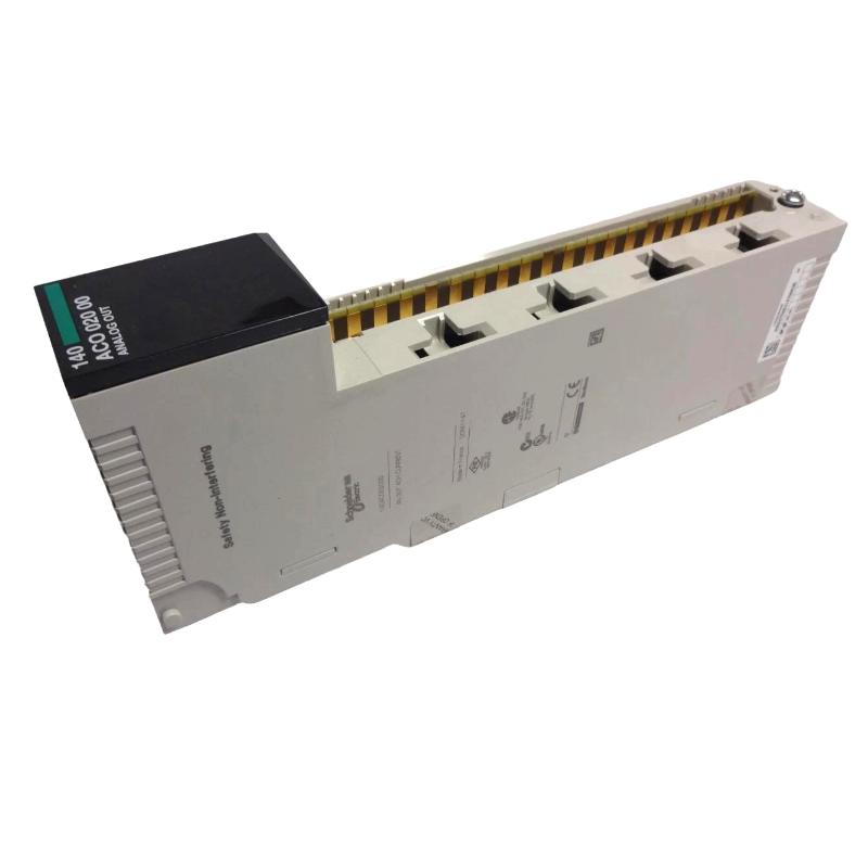
1. Product Overview
The Schneider Electric 140ACO02000C analog output module is a four-channel current output module in the Modicon Quantum automation platform. It is designed to convert digital output values from a programmable logic controller (PLC) into analog current signals for industrial control devices such as control valves, actuators, current-input instruments, and other process equipment. The Schneider Electric 140ACO02000C supports 4–20 mA output signals and enables a Quantum PLC system to regulate process variables by adjusting the current delivered to connected field devices. Typical applications include flow control, pressure regulation, temperature control, damper positioning, and other processes requiring an analog command signal. Correct installation involves verifying the exact catalog number, confirming the Quantum rack and power supply configuration, preparing the external current loops, mapping the module’s output words in the PLC, and testing each channel before placing the system into operation. The 140ACO02000C belongs to an established automation platform. Before planning a new installation or replacement, engineers should verify the availability of the exact module, the installed Quantum system configuration, and the suitability of any proposed replacement.
2. Technical Specifications
| Parameter | Specification |
|---|---|
| Manufacturer | Schneider Electric |
| Model | 140ACO02000C |
| Product type | Analog output module |
| Automation platform | Modicon Quantum |
| Number of output channels | 4 |
| Analog output range | 4–20 mA |
| Resolution | 12-bit class; confirm exact scaling and raw-value limits in the applicable documentation |
| Loop voltage | 12–30 V DC under specified operating conditions |
| Output addressing | 4 output words |
| Isolation | Channel and system isolation characteristics must be checked against the exact module documentation |
| Installation environment | Industrial control cabinet with suitable ventilation and electrical protection |
The specifications above summarize the product’s principal function. Exact terminal assignments, rack compatibility, electrical limits, and configuration requirements must be confirmed using the documentation for the installed 140ACO02000C revision.
3. Installation Preparation
3.1 Verify the Catalog Number and System Compatibility
Before installation, inspect the module label and confirm that the catalog number is 140ACO02000C. Do not assume that modules with similar catalog numbers have identical output ranges, channel configurations, or electrical characteristics. Check the following items:
- Confirm that the Quantum rack supports the module.
- Verify that the rack power supply has sufficient capacity for the complete installed configuration.
- Check the PLC hardware configuration and available output addresses.
- Confirm that connected field devices accept 4–20 mA signals.
- Verify the external loop voltage and load resistance requirements.
- Review the module’s wiring diagram and channel isolation requirements.
- Confirm the required process response if an output channel fails or loses control.
3.2 Prepare the Control Cabinet
Install the module in the designated slot of the compatible Quantum rack. Ensure that the rack is mounted securely and that wiring ducts, field terminals, and adjacent modules do not obstruct maintenance access. Keep analog signal wiring separated from high-current power conductors, variable-frequency drive output cables, and other sources of electrical interference. Where required by the installation design, use appropriately shielded twisted-pair cables and follow the grounding recommendations for the complete control system. Do not select a slot solely because it is physically available. The PLC configuration, rack design, and applicable module documentation must support the intended installation.
3.3 Apply Electrical Safety Procedures
Before inserting or removing the module, determine whether the rack supports the proposed maintenance procedure. If hot swapping is not explicitly supported for the exact configuration, shut down and isolate the system according to the manufacturer’s instructions. Apply lockout/tagout procedures where applicable and verify the safe state of external field circuits. Analog output wiring can be connected to powered field devices, so disconnecting the PLC rack alone may not remove every electrical hazard.
4. Wiring the 140ACO02000C Analog Output Module
4.1 Understand the Current Loop
The 140ACO02000C provides four analog current output channels. Each channel typically forms part of a current loop between the module and a compatible field device. A simplified functional arrangement is shown below:
Modicon Quantum PLC
        |
        v
140ACO02000C Analog Output Module
        |
        +---- Channel 1: 4–20 mA ---- Field Device 1
        |
        +---- Channel 2: 4–20 mA ---- Field Device 2
        |
        +---- Channel 3: 4–20 mA ---- Field Device 3
        |
        +---- Channel 4: 4–20 mA ---- Field Device 4
This is an illustrative functional diagram, not a terminal-level wiring schematic. Use the exact module wiring diagram to identify output terminals, return connections, and any required external loop components.
4.2 Check the Field Device Requirements
Before connecting a valve positioner, actuator, or other current-input device, verify its input range, polarity, input resistance, and power requirements. The total loop burden must remain within the module’s permitted operating limits. A high-resistance field device, long cable run, or additional series component can increase the voltage required to maintain the commanded current. The specified loop voltage range is 12–30 V DC under the applicable conditions. Do not exceed the documented voltage limits or assume that every field device can be connected directly without additional loop components.
4.3 Connect the Analog Signal Wiring
Follow the manufacturer’s terminal diagram when wiring each channel. Confirm that signal conductors are connected to the intended output and return terminals and that channel assignments correspond to the PLC program. Recommended practices include:
- Use conductors suitable for low-level industrial analog signals.
- Keep analog wiring away from switching and motor power conductors.
- Label each channel at both ends of the cable.
- Verify polarity and return wiring before energizing the loop.
- Check shield termination according to the system grounding design.
- Inspect for loose strands, accidental shorts, and damaged insulation.
Never infer terminal numbers from another module in the Quantum family. The correct wiring diagram for the exact catalog number takes precedence over a generic example.
4.4 Verify the Loop Load
A current output can only operate correctly when the total loop resistance and available loop voltage remain within the module’s specified limits. For a basic resistive load, the voltage required by the load is:
V_load = I_loop × R_load
For example, a 250-ohm input resistance requires 5 V at 20 mA, excluding cable resistance and other series voltage drops. The complete loop must still satisfy the module’s minimum and maximum operating requirements. This calculation is illustrative. Always include the actual field-device input characteristics, cable resistance, external supply arrangement, and any additional loop components when validating a real installation.
5. PLC Configuration and Output Scaling
5.1 Configure the Module in the Quantum System
Use the engineering software and configuration method appropriate to the installed Quantum PLC. Add or confirm the module in the correct rack and slot, then verify the output address allocation. The 140ACO02000C requires four output words, corresponding to its four output channels. The PLC program must assign the intended control value to the correct word for each channel. After downloading the hardware configuration, confirm that the PLC recognizes the module and that no configuration or communication faults are present.
5.2 Map Process Values to Output Current
The PLC program must translate the required process command into the raw value expected by the analog output module. For a linear 4–20 mA signal, the conceptual relationship is:
Output Current = 4 mA
               + (Normalized Command × 16 mA)
Here, the normalized command ranges from 0.0 to 1.0. A command of 0.0 corresponds to 4 mA, 0.5 corresponds to 12 mA, and 1.0 corresponds to 20 mA. The raw register scaling, numeric representation, and valid endpoint values must be verified against the exact module and PLC software documentation. Do not copy raw values from another analog output model without confirming that the scaling is identical.
5.3 Set Safe Output Behavior
Determine how the control system should behave when the PLC stops controlling the module, a channel fault occurs, or communication is lost. The selected response must be appropriate for the connected process. For a control valve, for example, the safe position depends on the process hazard analysis and valve design. A universal assumption that zero current, minimum current, or maximum current is always safe is not appropriate. Test the configured behavior during an approved commissioning procedure. Do not intentionally interrupt control of an operating process unless the test has been assessed and authorized.
6. Commissioning Procedure
6.1 Perform Pre-Energization Checks
Before applying power, complete the following checklist:
- Confirm the module catalog number and rack slot.
- Verify rack power supply capacity and module seating.
- Check output wiring against the approved diagram.
- Confirm field-device signal range and loop requirements.
- Verify output word assignments in the PLC configuration.
- Inspect grounding, shielding, and cable routing.
- Confirm that the process is in an approved commissioning state.
6.2 Confirm Module Status
Power the rack according to the approved startup procedure. Observe the module’s status indicators and verify that the PLC reports the module as operational. If a fault indicator appears, record the status before changing wiring or configuration. Review the rack power supply, module seating, slot assignment, and system diagnostics before proceeding to analog output testing.
6.3 Test Each Output Channel
Test the four channels individually using an approved test procedure and suitable measurement equipment. Where possible, verify the signal first with the field device safely isolated or with a suitable test load. A basic 4–20 mA functional check can use these illustrative test points:
| Normalized Command | Expected Current |
|---|---|
| 0% | 4 mA |
| 25% | 8 mA |
| 50% | 12 mA |
| 75% | 16 mA |
| 100% | 20 mA |
These values illustrate ideal linear scaling. Actual acceptance limits should be determined from the module accuracy specification, instrument uncertainty, and the site’s commissioning standard.
6.4 Verify Field Device Response
Once the output signal has been verified, reconnect the field device according to the approved procedure and check that its response matches the PLC command. Confirm the full operating range where it is safe to do so. For actuators and control valves, verify direction of movement, end limits, interlocks, and the process response before releasing the equipment for normal operation.
6.5 Record Commissioning Results
Document the rack and slot, channel assignments, PLC register addresses, tested output currents, field-device responses, and any deviations from expected behavior. The completed record provides a baseline for future maintenance and helps distinguish module faults from wiring, configuration, and field-device problems.
7. Integration with Industrial Control Systems
The 140ACO02000C can provide analog command signals for process equipment controlled by a Modicon Quantum PLC. In a process-control application, the PLC calculates a desired control output and writes the corresponding value to the module’s output register. Common applications include:
- Positioning compatible control valves and actuators.
- Adjusting process equipment that accepts a 4–20 mA reference.
- Regulating flow, pressure, or temperature through a control loop.
- Providing analog setpoints to compatible drives or instrumentation.
System integration requires more than matching the signal range. Confirm electrical compatibility, grounding, signal scaling, PLC execution behavior, and the safe response to module or communication faults.
8. Maintenance and Replacement Planning
The 140ACO02000C is an established Modicon Quantum product. Its commercial availability and service status can vary by market and date, so verify the current status before planning a new installation or a long-term maintenance strategy. Routine maintenance should include:
- Reviewing module and PLC diagnostic messages.
- Inspecting field wiring and terminal connections.
- Checking for corrosion, heat damage, or contamination.
- Verifying analog output accuracy during scheduled maintenance.
- Confirming that channel labels and PLC mappings remain correct.
- Recording recurring faults and corrective actions.
If replacing the module, verify the exact catalog number and configuration. A proposed substitute must be evaluated for output range, channel count, electrical isolation, rack compatibility, software configuration, wiring, and fault behavior. A newer module in another automation platform is not necessarily a direct plug-in replacement. Engineering validation and controlled commissioning may be required.
9. Frequently Asked Questions
How many output channels does the Schneider Electric 140ACO02000C provide?
The module provides four analog current output channels. Each channel can be assigned to a compatible field device that accepts a 4–20 mA command signal.
What signal does the 140ACO02000C generate?
It generates 4–20 mA analog current signals. Verify the field device’s input requirements and the module’s operating limits before connecting the loop.
Why is a field device not responding to the PLC output?
Possible causes include incorrect register mapping, incorrect scaling, an open loop, reversed wiring, an incompatible field device, or an output-channel fault. Test the signal and verify the complete circuit before replacing the module.
Can the module be replaced by a Modicon X80 analog output module?
A Modicon X80 analog output module may be considered as part of a migration project, but it should not be assumed to be a direct replacement. Rack architecture, controller compatibility, output ranges, wiring, software configuration, and process behavior must all be checked.
What should be checked if the measured current is lower than expected?
Check the commanded PLC value, raw register scaling, external loop voltage, total load resistance, terminal connections, and channel diagnostics. Compare measurements with the module’s specifications and the field device’s requirements.
10. Technical Summary
The Schneider Electric 140ACO02000C is a four-channel, 4–20 mA analog output module for the Modicon Quantum automation platform. Reliable operation depends on correct rack installation, verified current-loop wiring, accurate PLC output scaling, and thorough testing of each field channel. Engineers should confirm all terminal assignments and raw-value conventions using the exact module documentation. A structured commissioning process, regular signal verification, and careful replacement planning help maintain dependable analog control in industrial automation systems.