

ProductPRODUCT
Featured products



Contact Us
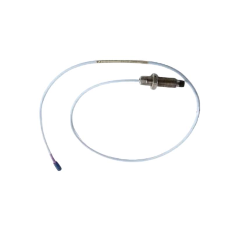
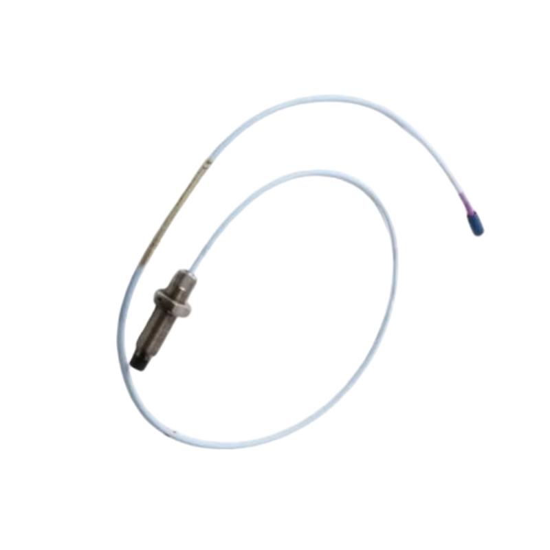
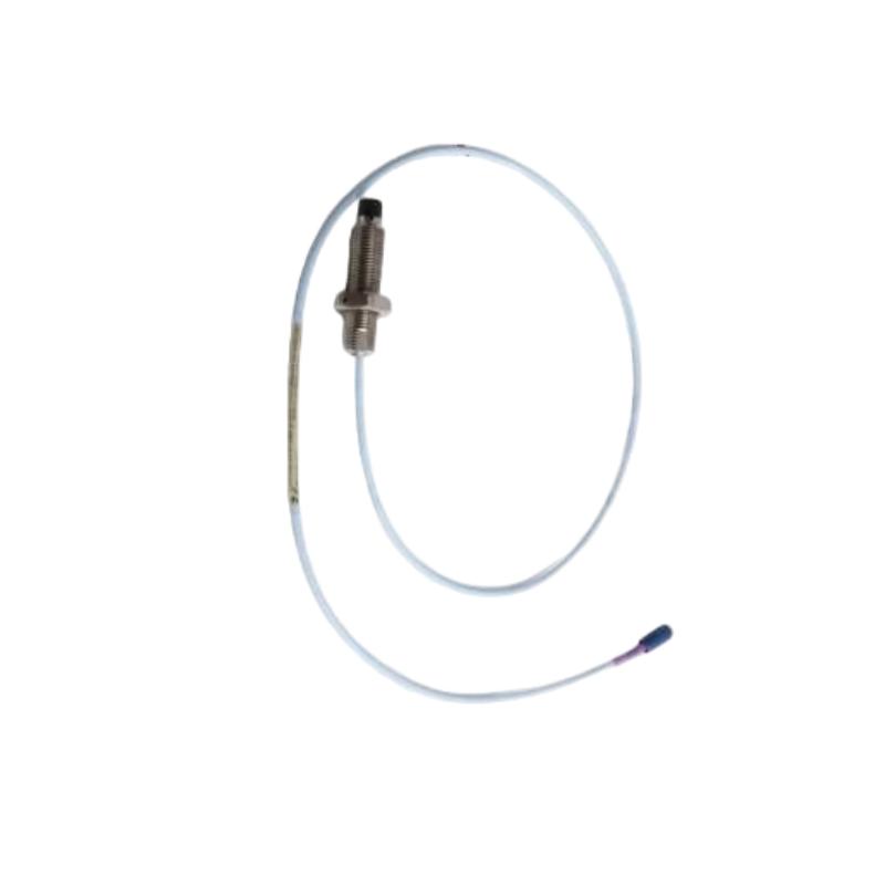
- Bently Nevada
- 330704-000-050-90-02-05
- 3300 XL 11 mm Proximity Probe
- USA
- 52mm
- 0.07kg
- Xiamen, China
- New & In Stock
- T/T, PayPal, Western Union
- 1 Year
- 1-3 Working Days
- DHL, UPS, TNT, FedEx and EMS.
- 24-Hour Service
- COO
- 6
Our advantage

Global Logistics
We have a 10-year logistics and express cooperation agreement, so our products can be shipped to any place in the world.

Brand new and original
Our products are imported in bulk from the place of origin. Because of the cooperative relationship, our products are all original and 100% new.

24-hour service
We provide 7*24 hours service to our customers. We will be there whenever you need us.

Price advantage
All our products are priced very favorably because we have our own warehouse and supply.
| Company Information | |||
| [email protected] | |||
| Mobile | +8615980777398 | ||
| +8615980777398 | |||
| 15980777398 |
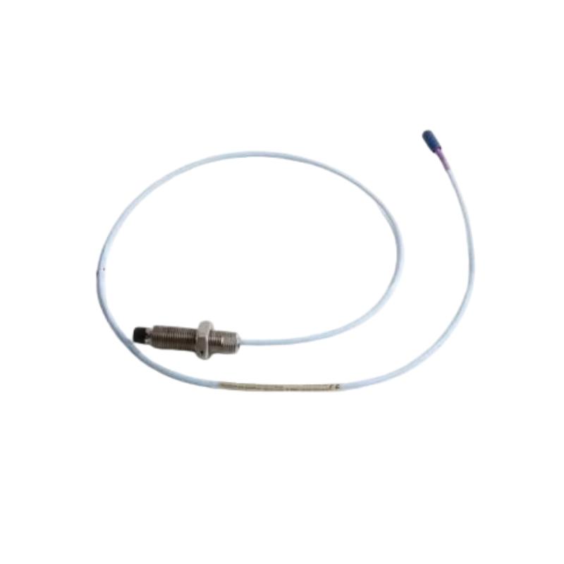
Bently Nevada 330704-000-050-90-02-05 Proximity Probe: Product Description, Technical Parameters, Applications and Related Models
1. Product Overview
The Bently Nevada 330704-000-050-90-02-05 is a model number presented for an industrial proximity probe application. Proximity probes are used in machinery monitoring systems to measure the distance between a sensor tip and a conductive target without making physical contact.
This type of sensor is commonly used on rotating equipment where shaft displacement, relative position, and changes in mechanical clearance need to be monitored. Typical installations include turbines, centrifugal compressors, industrial pumps, and other rotating machines operating under demanding conditions.
A proximity probe generally operates as part of a complete measurement system. Depending on the design, this system includes the probe, compatible extension cable, signal-conditioning electronics, and machinery monitoring equipment. Correct matching of these components is necessary for stable and reliable measurements.
The complete ordering code is important when selecting a replacement. Even models that appear similar can have different mechanical dimensions, cable arrangements, connector options, or electrical requirements.
Configuration note: The exact specifications of the complete model number have not been independently verified. The description below explains the general function and selection considerations for this type of equipment. Exact dimensions, weight, connector configuration, and the meaning of individual suffixes should be confirmed against the model-specific technical drawing before ordering.
2. Brand and Product Series
| Parameter | Description |
|---|---|
| Brand | Bently Nevada |
| Model | 330704-000-050-90-02-05 |
| Product category | Industrial proximity probe, subject to model verification |
| Product family | 3300 XL proximity transducer family; exact subseries to be confirmed |
| Measurement principle | Eddy-current proximity sensing, if confirmed for this configuration |
| Primary function | Non-contact distance or relative displacement measurement |
| Typical measurement target | Conductive metal surface, commonly a rotating shaft |
| System arrangement | Probe with compatible cabling and signal-conditioning electronics |
| Main application | Rotating machinery condition monitoring |
| Installation environment | Industrial machinery installations, within the specified operating limits |
| Dimensions | Exact dimensions require the model-specific drawing |
| Net weight | Exact weight in kg has not been confirmed |
| Replacement compatibility | Must be verified against the existing probe and monitoring system |
Product series description
The 3300 XL proximity transducer product family is associated with industrial machinery measurement and monitoring. Proximity sensing systems are used where non-contact measurement of shaft movement or position is required.
A probe should not be selected solely because its model number resembles another item in the same family. Thread specifications, case dimensions, cable length, connector type, and compatibility with the connected electronics must all be checked.
For model 330704-000-050-90-02-05, the exact subseries and configuration should be confirmed before the product is specified as a direct replacement.
3. Detailed Technical Parameters
The table below organizes the main technical information needed for purchasing, installation, and maintenance. Items that depend on the precise model configuration are marked accordingly rather than assigned unverified values.
| Technical parameter | Specification |
|---|---|
| Model | 330704-000-050-90-02-05 |
| Brand | Bently Nevada |
| Product type | Proximity probe; exact configuration requires confirmation |
| Product series | 3300 XL proximity transducer family; exact subseries unconfirmed |
| Sensing principle | Eddy-current, subject to model verification |
| Measurement method | Non-contact sensing of a conductive target |
| Typical target | Metal shaft or another suitable conductive surface |
| Measurement purpose | Relative displacement or distance measurement, depending on the system |
| Probe construction | Sensing tip, probe body, and cable termination, subject to configuration |
| Mounting style | Confirm from the model-specific drawing |
| Thread diameter | Not confirmed |
| Thread pitch | Not confirmed |
| Threaded section length | Not confirmed |
| Unthreaded section length | Not confirmed |
| Case length | Not confirmed |
| Overall probe length | Not confirmed |
| Probe-tip diameter | Not confirmed |
| Cable length | Requires confirmation from the complete ordering specification |
| Connector type | Requires confirmation |
| Electrical compatibility | Must match the specified cable, driver, and monitoring electronics |
| Output characteristics | Determined by the complete compatible transducer system |
| Operating temperature | Confirm the applicable product specification |
| Environmental suitability | Confirm against the intended installation conditions |
| Dimensions | Exact length, diameter, and connector clearance require the drawing |
| Net weight | Not confirmed (kg) |
| Installation requirement | Follow the specified mounting and gap-setting procedure |
| Maintenance | Inspect mounting, cabling, connectors, and signal stability |
| Replacement requirement | Verify the full ordering code and complete system compatibility |
Dimensions and weight
Dimensions and weight are important when a probe must fit an existing mounting port or replace an installed sensor without changing the machine structure.
For this exact model, the overall dimensions and net weight have not been confirmed. It would be misleading to assign precise measurements without the applicable drawing.
The following dimensional information should be obtained before purchasing:
| Measurement item | Required specification |
|---|---|
| Probe diameter | Exact diameter in mm |
| Mounting thread | Diameter and pitch |
| Threaded length | Length in mm |
| Unthreaded length | Length in mm, if applicable |
| Case length | Exact length in mm |
| Overall length | Total length according to the drawing’s measurement convention |
| Sensing-tip dimensions | Diameter and geometry in mm |
| Cable length | Exact length specified for the configuration |
| Connector envelope | Connector dimensions and installation clearance |
| Net product weight | Exact value in kg |
| Packaged shipping weight | Separate value if required for logistics |
The net product weight should not be confused with the packaged shipping weight. Both may be useful for purchasing and logistics records, but they describe different measurements.
4. Product Introduction
A proximity probe measures the distance between its sensing tip and a suitable target without requiring direct contact. In many rotating machinery applications, the target is a metal shaft.
As the shaft moves relative to the probe, the distance between the two surfaces changes. The sensing system detects the change, and compatible electronics convert the response into a signal that can be interpreted by the monitoring equipment.
This measurement approach is valuable because small changes in shaft position may provide useful information about the condition of a machine. Continuous measurements can help maintenance teams establish operating baselines, observe trends, and investigate unusual behavior.
The probe itself is normally only one part of the measurement chain. The associated cable, signal-conditioning electronics, mounting arrangement, target material, and monitoring configuration all affect the final result.
For this reason, model 330704-000-050-90-02-05 should be assessed as part of the complete installation rather than as an isolated component. Before selecting it for a new installation or replacement, confirm the actual product identity and its compatibility with the existing system.
5. Working Principle
If the exact configuration uses eddy-current sensing, the general measurement process works as follows.
1. Probe installation: The probe is positioned facing a conductive target, such as a rotating shaft.
2. Electromagnetic interaction: The sensing circuit produces an electromagnetic field that interacts with the conductive target.
3. Distance variation: As the target moves closer to or farther from the probe, the electrical response of the sensing system changes.
4. Signal conversion: Compatible electronics convert that response into a measurement signal.
5. Monitoring and analysis: The connected monitoring system displays or records the measurement for condition assessment.
This approach allows a measurement system to track relative shaft movement without physical contact with the shaft surface.
The actual measurement range, calibration characteristics, and output behavior depend on the specific probe and its compatible electronics. These details should be confirmed before the probe is commissioned.
6. Product Applications
6.1 Steam turbines
Steam turbines operate at high rotational speeds and under demanding mechanical and thermal conditions. Shaft movement is one of the parameters that may be monitored to assess the condition of the rotating assembly.
A properly selected proximity probe can contribute to relative shaft-displacement measurements. Changes in the recorded signal may lead maintenance personnel to investigate bearing conditions, shaft alignment, rotor behavior, or other mechanical factors.
The probe provides measurement information rather than a complete diagnosis. Its readings should be evaluated alongside other machine data and the plant’s maintenance procedures.
6.2 Gas turbines
Gas turbines are widely used in power generation and industrial installations where dependable operation is important.
A suitable proximity measurement system can help monitor shaft behavior during operation. The resulting information can be used to observe changes from established operating trends and determine whether further inspection is needed.
The probe must be appropriate for the installation location and the environmental limits of the complete measurement system.
6.3 Centrifugal compressors
Centrifugal compressors are used in gas processing, petrochemical production, chemical plants, and other industrial facilities.
Shaft-displacement measurements can help engineers assess changes in rotor behavior and investigate abnormal operating conditions. When combined with other measurements, they can contribute to a more complete understanding of machine performance.
The correct probe configuration depends on the compressor’s design, target geometry, mounting arrangement, and monitoring equipment.
6.4 Industrial pumps
Large industrial pumps may operate continuously in water-treatment plants, power stations, manufacturing facilities, and process industries.
Where the machine design calls for proximity sensing, a suitable probe can support the monitoring of relative shaft movement. The measurement can provide useful information when investigating changes in operating behavior.
Probe selection should take into account the mounting port, available space, measurement requirements, and compatibility with the installed monitoring system.
6.5 Gearboxes and rotating equipment
Some gearboxes and other rotating machines use displacement or position measurements as part of their condition-monitoring arrangements.
The suitability of this probe depends on the machine’s mechanical design and the intended measurement point. A probe designed for one configuration should not automatically be assumed suitable for another.
6.6 Machinery monitoring and protection systems
A proximity probe can supply data to a larger monitoring arrangement. Depending on the connected electronics and system design, the measurement may be used for display, trend analysis, alarm functions, or machinery protection.
Any automatic protective action depends on the connected equipment, configured limits, and approved plant logic. The probe alone does not independently provide a shutdown function.
7. Product Advantages
7.1 Non-contact measurement
The probe can measure a suitable target without physically touching it. This makes proximity sensing useful for rotating shafts where a contact-based measurement method would introduce wear or interfere with operation.
7.2 Continuous monitoring capability
When connected to compatible monitoring electronics, the probe can provide measurements during machine operation. Continuous data can help engineers observe trends that might not be apparent during occasional manual inspections.
7.3 Useful shaft-displacement information
Relative shaft displacement is an important measurement in many rotating machinery applications. When the probe is installed at the appropriate location, its data can contribute to an assessment of machine behavior.
7.4 Integration with a wider monitoring system
The probe can form part of a larger measurement chain that includes cabling, signal-conditioning electronics, and monitoring equipment.
This arrangement allows the measurement to be considered alongside other information, such as vibration, temperature, rotational speed, and operating load.
7.5 Support for maintenance planning
Historical readings can help maintenance teams establish normal operating trends and identify changes that deserve further investigation.
This information can support condition-based maintenance planning, although the final maintenance decision should also consider machine operating conditions and other diagnostic evidence.
7.6 Compact installation concept
A proximity probe can be installed in a suitable mounting location while measuring a target without contact. The actual space requirement depends on the exact probe dimensions, mounting design, cable route, and connector clearance.
7.7 Early indication of abnormal behavior
A change in measured shaft position may indicate that further inspection is necessary. However, signal changes can also be caused by mounting problems, damaged cables, electrical interference, or incorrect system setup.
Reliable troubleshooting therefore requires inspection of the complete measurement chain rather than assuming every abnormal reading indicates a mechanical fault.
8. Installation and Maintenance Recommendations
Mechanical installation
Confirm the mounting thread, installation depth, probe orientation, and required clearance before fitting the probe. The mounting arrangement should follow the applicable equipment drawing.
Probe gap adjustment
Set the probe gap according to the specifications for the complete transducer system. An incorrect gap can affect measurement quality or prevent the system from operating within its intended range.
Cable routing
Protect the cable from abrasion, excessive bending, heat, mechanical damage, and environmental exposure. Follow the applicable installation requirements for routing and interference control.
Connector inspection
Inspect the connector for contamination, corrosion, physical damage, and secure engagement. Similar-looking connectors should not be assumed to have identical electrical characteristics.
System compatibility
Verify that the probe, extension cable, driver, and monitoring equipment are compatible with one another. Mechanical fit alone does not guarantee correct electrical performance.
Commissioning
After installation, check the measurement signal using the approved commissioning procedure. Record baseline readings where required by the plant’s maintenance process.
Routine maintenance
Inspect the mounting, cable, connector, and signal stability at suitable intervals. If a reading becomes abnormal, investigate possible mechanical, electrical, and installation-related causes before replacing the sensor.
9. Five Related Models for Technical Comparison
The following table lists five models that may be considered for a preliminary comparison of proximity probes and related monitoring configurations. They are not confirmed as direct substitutes for model 330704-000-050-90-02-05.
| No. | Model | Product category | Parameters to compare | Dimensions | Weight (kg) | Selection notes |
|---|---|---|---|---|---|---|
| 1 | 330704-000-050-90-02-05 | Reference model; exact configuration to be verified | Complete code, thread, case length, cable, connector | Exact drawing required | Not confirmed | Confirm the exact product identity before purchase |
| 2 | 330704-000-050-90-02-00 | Related model code | Compare suffix options and all mechanical specifications | Exact drawing required | Not confirmed | Do not assume the final suffix is interchangeable |
| 3 | 330703-000-050-10-02-00 | Related proximity probe configuration | Mounting dimensions, cable arrangement, connector, system compatibility | Exact drawing required | Not confirmed | Confirm the exact probe design |
| 4 | 330703-000-052-10-02-00 | Related proximity probe configuration | Case length, thread, cable, and connector arrangement | Exact drawing required | Not confirmed | Verify the physical fit and electrical configuration |
| 5 | 330701-00-30-10-02-CN | Related proximity probe configuration | Intended measurement, mounting, cable, and system compatibility | Exact drawing required | Not confirmed | Treat as a comparison candidate until verified |
| 6 | 330907-05-30-10-02-CN | Related proximity probe configuration | Product identity, installation dimensions, electrical compatibility | Exact drawing required | Not confirmed | Confirm suitability for the required application |
How to compare the related models
For a direct replacement, compare the complete part number first. Thread diameter, thread pitch, case length, mounting depth, cable length, and connector arrangement must match the installation requirements.
Next, verify the electrical compatibility of the probe and the connected monitoring equipment. A probe that fits mechanically may still be unsuitable for the installed measurement system.
For a new installation, begin with the measurement requirements, target material, available mounting space, and environmental conditions. Select the probe according to these requirements rather than relying on similarities between model codes.
10. Five Additional Models from the Same Brand
The models below are additional comparison candidates associated with industrial machinery monitoring. This is not a verified ranking of the brand’s most popular products, and the exact role of each model should be confirmed before purchasing.
| No. | Model | Product area | Main comparison point | Dimensions | Weight (kg) | Important considerations |
|---|---|---|---|---|---|---|
| 1 | 330701-00-30-10-02-CN | Proximity sensing | Probe configuration and intended measurement application | Exact drawing required | Not confirmed | Verify the complete specification |
| 2 | 330101-00-30-10-02-CN | Proximity sensing | Mounting arrangement and system compatibility | Exact drawing required | Not confirmed | Confirm the product series and dimensions |
| 3 | 330907-05-30-10-02-CN | Proximity sensing | Probe design and installation requirements | Exact drawing required | Not confirmed | Check connector, cable, and electrical characteristics |
| 4 | 330130-040-00-00 | Proximity-system component | Component function within the measurement system | Exact drawing required | Not confirmed | Confirm the exact component type before considering substitution |
| 5 | 330180-50-00 | Proximity-system component | Intended function and compatibility with the installed system | Exact drawing required | Not confirmed | Verify the model-specific technical details |
These models can serve as a starting point for a wider technical comparison. They should not be described as the five best-selling products without verified sales data, and they should not be assumed to perform the same function as the reference model.
11. Purchasing Checklist
Before ordering model 330704-000-050-90-02-05, confirm the following information.
| Item | Required check | Why it matters |
|---|---|---|
| Full model number | Match all characters, including the final suffix | Different suffixes can indicate different configurations |
| Product identity | Confirm the exact probe type and product series | Prevents confusion between related components |
| Thread specification | Confirm diameter and pitch | Ensures mechanical fit |
| Case dimensions | Confirm length and diameter | Prevents clearance and installation problems |
| Cable | Confirm length and construction | Supports correct routing and system configuration |
| Connector | Verify the specified termination | Avoids connection incompatibility |
| Monitoring electronics | Confirm electrical compatibility | Ensures correct operation of the complete system |
| Environment | Check temperature and installation conditions | Establishes suitability for the intended location |
| Approval requirements | Confirm any required certification | Important for installations subject to specific plant requirements |
| Overall dimensions | Obtain the model-specific drawing | Needed for replacement planning |
| Net weight | Obtain the exact value in kg | Needed for inventory and logistics |
| Documentation | Confirm the technical specification and installation procedure | Supports correct commissioning and maintenance |
12. Conclusion
The Bently Nevada 330704-000-050-90-02-05 is being assessed here as a proximity probe model for industrial machinery monitoring. Proximity sensing can provide non-contact measurements of a conductive target and support the monitoring of shaft position or relative displacement in suitable rotating machinery applications.
Its potential applications include turbines, compressors, pumps, and other industrial equipment where shaft movement is an important operating parameter. The principal advantages of proximity sensing include non-contact operation, continuous measurement capability, and the ability to supply useful data for condition assessment and maintenance planning.
The most important consideration before purchasing is to verify the complete configuration. The exact product series, mounting thread, case dimensions, cable length, connector type, and compatibility with the existing monitoring equipment should all be confirmed.
The exact dimensions and net weight in kilograms for this complete model number remain unconfirmed. These values should be entered into the final technical specification only after they have been checked against the model-specific drawing or product documentation. The related models listed above should likewise be treated as comparison candidates rather than guaranteed replacements.