

ProductPRODUCT
Featured products



Contact Us
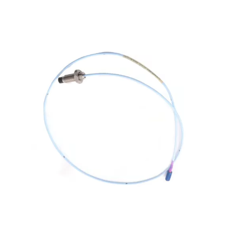
- Bently Nevada
- 330703-000-052-10-02-00
- 3300 XL 11 mm Proximity Probe
- USA
- 52 mm
- 0.070 kg
- Xiamen, China
- New & In Stock
- T/T, PayPal, Western Union
- 1 Year
- 1-3 Working Days
- DHL, UPS, TNT, FedEx and EMS.
- 24-Hour Service
- COO
- 5
Our advantage

Global Logistics
We have a 10-year logistics and express cooperation agreement, so our products can be shipped to any place in the world.

Brand new and original
Our products are imported in bulk from the place of origin. Because of the cooperative relationship, our products are all original and 100% new.

24-hour service
We provide 7*24 hours service to our customers. We will be there whenever you need us.

Price advantage
All our products are priced very favorably because we have our own warehouse and supply.
| Company Information | |||
| [email protected] | |||
| Mobile | +8615980777398 | ||
| +8615980777398 | |||
| 15980777398 |
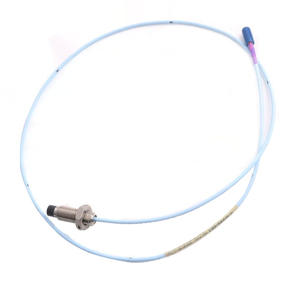
Bently Nevada 330703-000-052-10-02-00 Proximity Probe: Technical Specifications, Product Overview, Applications, Advantages, and Related Models
1. Product Overview
The Bently Nevada 330703-000-052-10-02-00 is a model designation associated with industrial proximity measurement equipment. Before using this designation in a purchasing specification, it is important to confirm the exact product family and configuration, as the complete ordering code determines the probe type, mechanical dimensions, cable arrangement, connector, and other technical options.
Proximity probes are widely used in rotating machinery monitoring systems to measure the relative position and displacement of a conductive shaft. When connected to compatible signal-conditioning electronics, a proximity probe can provide information used to monitor shaft vibration, relative shaft position, and changes in machine operating behavior.
These measurements are particularly valuable in installations where rotating equipment operates continuously and mechanical reliability is essential. Typical applications include turbines, centrifugal compressors, industrial pumps, large motors, and other critical rotating machinery.
A proximity measurement system generally consists of a probe, a compatible extension cable, and a Proximitor sensor. The sensor processes the probe’s electrical response and provides a measurement signal to the monitoring equipment.
The complete system can help maintenance personnel identify unusual changes in shaft movement, compare current measurements with historical trends, and investigate potential mechanical problems.
The exact technical specifications of model 330703-000-052-10-02-00 should not be inferred solely from its model number. In particular, the probe family, measurement range, mounting thread, overall length, connector configuration, and net weight must be confirmed before the model is treated as a replacement for another proximity probe.
2. Brand and Product Series
| Item | Product information |
|---|---|
| Brand | Bently Nevada |
| Product series | 3300 XL |
| Product family | 3300 XL 11 mm Proximity Transducer System |
| Model | 330703-000-052-10-02-00 |
| Product type | Industrial proximity probe |
| Sensing technology | Eddy-current displacement measurement |
| Mounting thread | M14 × 1.5, associated with the 330703 model family |
| Probe construction | Unarmored configuration |
| Primary function | Non-contact shaft displacement measurement |
| Cable configuration | 1.0 m total-length option |
| Connector | Miniature coaxial ClickLoc connector, standard cable configuration |
| Approval option | 00 — no agency approval option specified |
| Dimensions | 52 mm case-length option; 1.0 m total-length option; complete drawing required |
| Weight (kg) | Approximately 0.070 kg for a related minimum-length configuration; exact weight for this 52 mm configuration requires confirmation |
The 3300 XL 11 mm family is intended for industrial applications requiring non-contact measurement of shaft displacement and vibration. Its suitability for a particular machine depends on the complete probe configuration and the compatibility of the associated transducer electronics.
3. Detailed Technical Specifications
The model number 330703-000-052-10-02-00 can be interpreted using the ordering structure associated with the 330703 model family. The principal configuration fields are summarized below.
| Parameter | Specification |
|---|---|
| Complete part number | 330703-000-052-10-02-00 |
| Base model | 330703 |
| Product series | 3300 XL |
| Probe family | 11 mm proximity probe |
| Mounting thread | M14 × 1.5 |
| Armor | Unarmored |
| Unthreaded length option | 000 — 0 mm |
| Overall case length option | 052 — 52 mm |
| Total length option | 10 — 1.0 m (3.3 ft) |
| Connector and cable option | 02 — miniature coaxial ClickLoc connector, standard cable |
| Approval option | 00 — no agency approval option specified |
| Measurement principle | Eddy-current sensing |
| Measurement target | Conductive metallic shaft |
| Main measurement | Relative shaft displacement |
| Dynamic measurement | Shaft vibration, when used with a compatible monitoring system |
| Linear range | Confirm the specification for the exact probe and matched electronics |
| Scale factor | Confirm against the applicable system specification |
| Operating temperature | Verify the permitted range for the exact configuration |
| Probe tip material | Verify the applicable product specification |
| Probe case material | Verify the applicable product specification |
| Recommended installation torque | Follow the applicable installation specification |
| Dimensions | 52 mm case-length option; complete dimensions require the model drawing |
| Weight (kg) | Exact weight for the 52 mm configuration is not confirmed |
| Shipping dimensions | Depend on the packaging configuration |
| Shipping weight (kg) | Must be recorded separately from net product weight |
3.1 Mechanical Dimensions
The 52 mm case-length option is a key identification detail for this model. It should not be confused with the complete probe assembly length, which also includes the cable and connector arrangement.
For installation planning, the following dimensions should be checked separately:
– Mounting thread diameter and pitch.
– Unthreaded section length.
– Overall case length.
– Total probe and cable length.
– Probe tip geometry.
– Connector clearance.
– Required installation gap.
The complete mechanical drawing should be used when replacing an existing probe, especially where the available mounting space is limited.
3.2 Weight
The net weight of a related minimum-length 330703 configuration is approximately 0.070 kg. However, that value should not be treated as the verified net weight of the specific 52 mm case configuration.
For an accurate product catalogue, the weight should be entered as To be confirmed until the exact configuration has been weighed or checked against its product record.
4. Product Introduction
The 330703-000-052-10-02-00 is a proximity probe configuration associated with the 3300 XL 11 mm measurement family. It is designed to detect changes in the distance between the probe tip and a conductive metallic target.
The probe is intended for applications where shaft movement must be monitored without physical contact between the sensing element and the rotating shaft.
In industrial rotating machinery, changes in shaft displacement can provide useful information about rotor behavior, vibration, relative shaft position, and possible mechanical deterioration. When the probe is connected to compatible electronics, the resulting signal can be processed by a machinery monitoring system.
The 3300 XL 11 mm family is used in applications that require its particular probe geometry and measurement characteristics. Correct selection depends on the mounting thread, case length, cable configuration, connector, and compatibility with the associated Proximitor sensor.
The probe should therefore be treated as part of a complete measurement system rather than an independent vibration monitor.
5. Operating Principle
5.1 Eddy-Current Sensing
The probe uses an electromagnetic sensing field to detect the distance between its tip and a conductive target.
An alternating electrical signal energizes the sensing coil inside the probe. The resulting electromagnetic field interacts with the conductive shaft surface. Changes in the distance between the probe and the shaft alter the electrical response of the sensing system.
A compatible Proximitor sensor processes this response and converts it into a measurement signal.
The measurement process follows five main stages:
1. The probe is installed near the shaft at the designated measurement point.
2. The compatible electronics energize the probe.
3. Shaft movement changes the electromagnetic interaction between the probe and the target.
4. The electronics convert the change into a corresponding electrical signal.
5. The monitoring system displays or evaluates the resulting measurement.
Correct installation, calibration, target material, and system compatibility are essential for reliable results.
5.2 Static Shaft Position
Static position measurements indicate the relative position of the shaft with respect to the probe.
This information can help engineers evaluate shaft positioning and changes in mechanical clearance, provided the installation is configured for the required measurement.
5.3 Dynamic Shaft Displacement
Dynamic displacement measurements track shaft movement over time.
When the shaft vibrates, the gap between the probe tip and the shaft changes. The monitoring system can use this changing signal to assess shaft vibration and identify unusual operating trends.
Such measurements can support investigations into rotor imbalance, misalignment, bearing-related problems, and other mechanical conditions. Diagnosis should be based on the complete monitoring data and appropriate engineering assessment.
6. Main Applications
6.1 Steam Turbines
Steam turbines operate under changing loads and temperatures. Shaft displacement measurements can help maintenance teams monitor rotor movement during startup, normal operation, load changes, and shutdown.
A compatible monitoring system can use probe signals to observe vibration trends and investigate changes in shaft position.
6.2 Gas Turbines
Gas turbines require reliable monitoring of rotating components. Proximity measurements can provide information about shaft displacement and vibration at designated measurement points.
The probe must be suitable for the installation’s temperature, mounting arrangement, target material, and associated electronics.
6.3 Centrifugal Compressors
Centrifugal compressors are commonly used in continuous industrial processes. Shaft vibration monitoring can help engineers investigate changes in rotor behavior and identify conditions requiring further inspection.
The probe can contribute to a broader condition-monitoring strategy when installed in a suitable bearing or shaft measurement location.
6.4 Industrial Pumps
Large process pumps may experience vibration caused by imbalance, misalignment, bearing wear, hydraulic disturbances, or changing operating conditions.
Where the pump design supports proximity measurement, the probe can provide non-contact shaft displacement information for monitoring and troubleshooting.
6.5 Large Electric Motors
Large motors used in industrial plants may require monitoring of shaft movement and vibration.
The suitability of a proximity probe depends on the motor’s shaft geometry, bearing design, and monitoring architecture. It is not automatically the preferred sensor for every motor.
6.6 Machinery Protection Systems
When incorporated into a suitable protection system, proximity measurements can contribute to alarm monitoring and protective functions.
The probe itself does not perform shutdown logic. Alarm thresholds, signal validation, trip logic, and protective actions depend on the installed monitoring and protection equipment.
7. Product Advantages
| Advantage | Description |
|---|---|
| Non-contact sensing | Measures the distance to a conductive target without direct contact during normal operation |
| Continuous monitoring | Provides measurement data when connected to a compatible monitoring system |
| Shaft displacement measurement | Supports monitoring of relative shaft movement |
| Vibration monitoring | Provides dynamic displacement information for suitable monitoring applications |
| Industrial integration | Can be integrated with compatible extension cables and Proximitor sensors |
| Compact sensing arrangement | Fits designated probe mounting locations on suitable machinery |
| Trend monitoring | Allows measurement values to be compared over time |
| Maintenance support | Provides additional information for troubleshooting and maintenance planning |
| Replacement flexibility | The configuration-based ordering system supports selection of different mounting and cable options |
| System-based monitoring | Can form part of a broader machinery monitoring and protection arrangement |
The main advantage of this type of probe is the ability to obtain shaft displacement information without contact with the rotating shaft. Its practical value depends on correct installation and the performance of the complete measurement system.
8. Installation and Maintenance Considerations
| Item | Recommended practice |
|---|---|
| Mounting | Verify thread and installation dimensions before fitting the probe |
| Probe gap | Set according to the applicable system procedure |
| Cable routing | Avoid damage, excessive bending, and unsuitable environmental exposure |
| Connector | Verify the mating connection and secure installation |
| Proximitor sensor | Confirm compatibility with the probe and cable |
| Calibration | Use the correct system-specific calibration procedure |
| Functional testing | Verify signal stability and measurement response after installation |
| Troubleshooting | Check the probe, cable, electronics, and monitoring channel together |
| Dimensions | Use the exact drawing for the 52 mm configuration |
| Weight (kg) | Confirm the net weight of the exact model |
9. Five Related Models from the Same Series or Product Family
The following models are candidates for comparison within the 3300 XL 11 mm family and related proximity measurement systems. Their configurations differ, so they should not be assumed to be direct substitutes for the original model.
| No. | Model | Series | Main parameters | Dimensions | Weight (kg) |
|---|---|---|---|---|---|
| 1 | 330703-000-052-10-02-00 | 3300 XL 11 mm | M14 × 1.5 thread; unarmored; 52 mm case-length option; 1.0 m cable; standard ClickLoc connector | 52 mm case-length option; complete drawing required | Exact value to be confirmed |
| 2 | 330703-000-050-10-02-00 | 3300 XL 11 mm | M14 × 1.5 thread; unarmored; 50 mm case-length option; 1.0 m cable; standard ClickLoc connector | 50 mm case-length option | Approx. 0.070 kg for the minimum-length configuration; verify exact net weight |
| 3 | 330703-000-070-10-02-00 | 3300 XL 11 mm | M14 × 1.5 thread; unarmored; 70 mm case-length option; 1.0 m cable; standard ClickLoc connector | 70 mm case-length option | Exact value to be confirmed |
| 4 | 330704-000-050-10-02-00 | 3300 XL 11 mm | Related armored probe configuration; 50 mm case-length option; 1.0 m cable option; verify connector and approval details | Exact drawing required | Exact value to be confirmed |
| 5 | 330709-000-050-10-02-00 | 3300 XL 11 mm | Related M16 × 1.5 mounting configuration; unarmored; 50 mm case-length option; verify complete ordering code | Exact drawing required | Exact value to be confirmed |
9.1 Model 330703-000-050-10-02-00
This configuration has a 50 mm case-length option and is suitable for comparison where the installation requires the corresponding 3300 XL 11 mm probe arrangement.
The difference between the 50 mm and 52 mm case options may matter when fitting the probe into an existing mounting location. The installation drawing should be checked before substitution.
9.2 Model 330703-000-070-10-02-00
This model has a 70 mm case-length option. It may be relevant where a longer case configuration is required by the machine mounting arrangement.
The mounting thread, cable configuration, and electrical compatibility should be checked against the original equipment requirements.
9.3 Model 330704-000-050-10-02-00
The 330704 family is associated with an armored 3300 XL 11 mm probe configuration.
Armor may be relevant where the cable or probe assembly requires additional mechanical protection. The complete configuration should be verified before using it as a replacement for an unarmored model.
9.4 Model 330709-000-050-10-02-00
The 330709 family is associated with an M16 × 1.5 mounting configuration. This makes thread compatibility a key consideration.
It should be evaluated only where the machine’s mounting arrangement is suitable for that thread specification.
9.5 Model Selection Summary
When choosing among these models, prioritize the exact thread, case length, cable arrangement, connector, and system compatibility. A related model can be useful for comparison, but it is not necessarily an approved replacement.
10. Five Additional Models from the Same Brand
These additional products cover different proximity probe configurations and supporting components used in industrial machinery monitoring. They are comparison candidates, not a verified sales-volume ranking.
| No. | Model | Product category | Main parameters | Dimensions | Weight (kg) |
|---|---|---|---|---|---|
| 1 | 330101-00-30-10-02-CN | 3300 XL 8 mm proximity probe | 8 mm probe family; non-contact shaft displacement measurement; system-specific cable and electronics required | Exact drawing required | To be confirmed |
| 2 | 330701-00-30-10-02-CN | 3300 XL 11 mm proximity probe family | Related 11 mm family designation; exact configuration and compatibility require confirmation | Exact drawing required | To be confirmed |
| 3 | 330907-05-30-10-02-CN | 3300 NSv proximity probe | NSv proximity measurement family; model-specific mounting and electronics required | Exact drawing required | To be confirmed |
| 4 | 330130-040-00-00 | 3300 XL extension cable family | Extension cable for a compatible proximity measurement system; cable length and connector configuration must be verified | Exact cable specification required | To be confirmed |
| 5 | 330180-50-00 | 3300 XL Proximitor sensor family | Electronic interface for compatible probes; confirm probe family and complete system configuration | Exact housing drawing required | To be confirmed |
10.1 Model 330101-00-30-10-02-CN
This model belongs to the 3300 XL 8 mm proximity probe family. It is relevant to installations designed for that specific probe family.
The 8 mm and 11 mm probe families have different system requirements. Before considering this model as a replacement, confirm the probe family, Proximitor sensor, extension cable, and calibration requirements.
10.2 Model 330701-00-30-10-02-CN
This is a related 3300 XL 11 mm family designation. It may be useful for comparison when reviewing a similar installation.
The complete model configuration should be confirmed before ordering, particularly where mounting dimensions, cable configuration, or approvals differ.
10.3 Model 330907-05-30-10-02-CN
This model designation is associated with the 3300 NSv proximity probe family.
The NSv family has its own mounting and measurement characteristics. It should be selected only for an installation designed to use the corresponding system.
10.4 Model 330130-040-00-00
An extension cable connects a compatible proximity probe to its associated electronic unit.
Cable length, connector configuration, and electrical compatibility must be verified as part of the complete transducer system. An incorrect cable configuration can affect the measurement system’s performance.
10.5 Model 330180-50-00
A Proximitor sensor provides the electronic interface required by a compatible proximity probe. It processes the probe’s response and produces the corresponding measurement signal.
When troubleshooting a measurement fault, it is important to assess the probe, cable, Proximitor sensor, and monitoring channel together.
11. Final Product Summary
The Bently Nevada 330703-000-052-10-02-00 is associated with the 3300 XL 11 mm proximity probe family. Its identified configuration includes an M14 × 1.5 mounting thread, an unarmored construction, a 52 mm case-length option, a 1.0 m total-length option, and a miniature coaxial ClickLoc connector with standard cable.
Its primary function is non-contact shaft displacement measurement. When used with compatible electronics, it can contribute to shaft vibration monitoring and machinery condition assessment in industrial rotating equipment.
The five related models provide alternatives for comparing case length, mounting configuration, and armored construction. The five additional models cover other proximity probe families and supporting measurement-system components.
For procurement and technical documentation, the most important remaining details to confirm are the exact physical dimensions, net weight in kilograms, measurement range, and compatibility with the existing transducer system. These values should be verified for the complete model configuration rather than estimated from a similar part number.