

ProductPRODUCT
Featured products



Contact Us
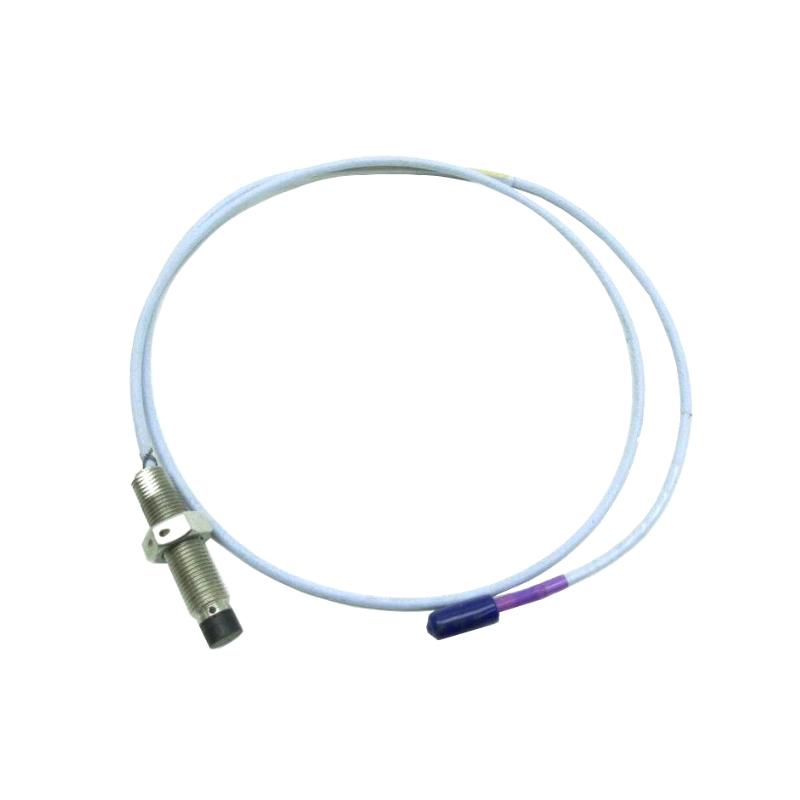
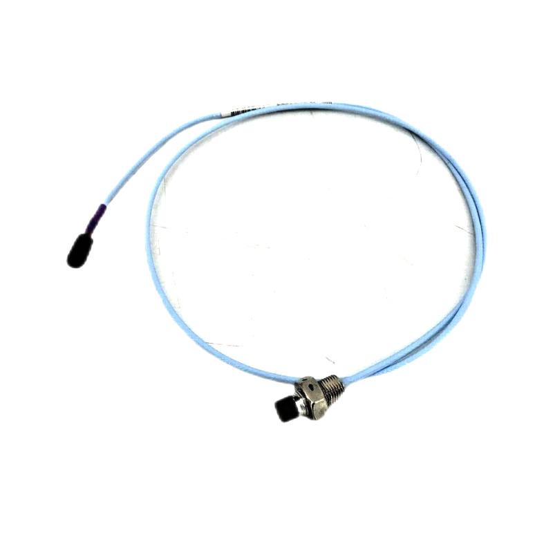
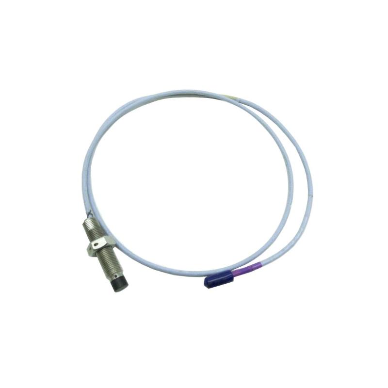
- Bently Nevada
- 330701-00-30-10-02-CN
- 3300 XL 11 mm Proximity Probe
- USA
- 8 mm
- 0.45kg
- Xiamen, China
- New & In Stock
- T/T, PayPal, Western Union
- 1 Year
- 1-3 Working Days
- DHL, UPS, TNT, FedEx and EMS.
- 24-Hour Service
- COO
- 6
Our advantage

Global Logistics
We have a 10-year logistics and express cooperation agreement, so our products can be shipped to any place in the world.

Brand new and original
Our products are imported in bulk from the place of origin. Because of the cooperative relationship, our products are all original and 100% new.

24-hour service
We provide 7*24 hours service to our customers. We will be there whenever you need us.

Price advantage
All our products are priced very favorably because we have our own warehouse and supply.
| Company Information | |||
| [email protected] | |||
| Mobile | +8615980777398 | ||
| +8615980777398 | |||
| 15980777398 |
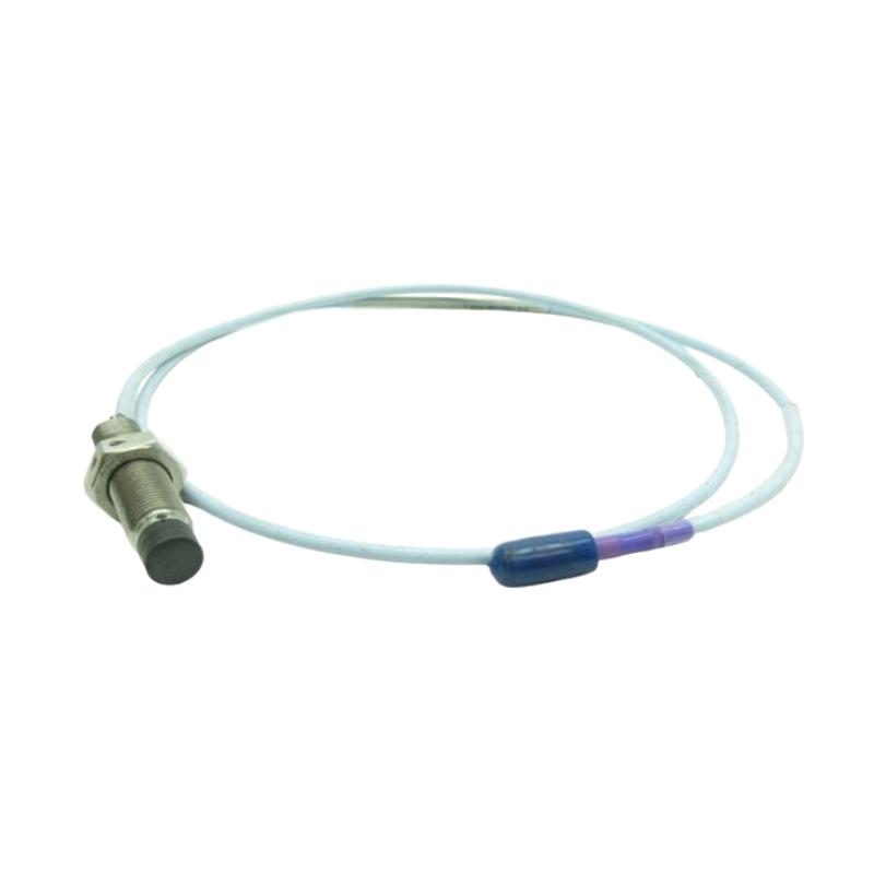
Bently Nevada 330701-00-30-10-02-CN Proximity Probe: Technical Specifications, Product Description, Applications, Advantages, and Related Models
1. Product Overview
The Bently Nevada 330701-00-30-10-02-CN is a model designation associated with the 3300 XL 11 mm proximity probe product family. Proximity probes are used in industrial machinery monitoring systems to measure shaft displacement and the relative position of a rotating shaft in relation to a stationary reference point.
This type of sensor is particularly useful in industrial environments where rotating equipment operates continuously and small changes in shaft movement can provide important information about machine condition. Typical applications include steam turbines, gas turbines, centrifugal compressors, industrial pumps, and large electric motors.
The probe operates on the eddy-current measurement principle. When installed near a conductive metallic target, it detects changes in the distance between the probe tip and the target. A compatible Proximitor sensor processes the probe response and generates a measurement signal for a machinery monitoring system.
The resulting data can be used to observe shaft vibration, monitor relative shaft position, evaluate operating trends, and support maintenance decisions.
The probe is one component of a complete measurement system. Correct performance depends on the compatibility of the probe, extension cable, Proximitor sensor, installation geometry, and monitoring equipment.
The complete model number must be used when identifying the replacement component. Similar-looking models may have different mounting dimensions, cable configurations, connectors, or electrical characteristics. The exact configuration of the specified part should therefore be checked before purchase or installation.
2. Basic Product Information
| Parameter | Description |
|---|---|
| Product name | Industrial proximity probe |
| Model | 330701-00-30-10-02-CN |
| Brand | Bently Nevada |
| Product series | 3300 XL proximity measurement family |
| Product category | Non-contact displacement sensor |
| Sensor technology | Eddy-current proximity sensing |
| Primary function | Shaft displacement and relative position measurement |
| Measurement target | Electrically conductive metallic surface |
| Typical installation | Near a rotating shaft or designated conductive target |
| Main application | Machinery condition monitoring |
| Compatible system components | Probe, compatible extension cable, and Proximitor sensor |
| Typical equipment | Turbines, compressors, pumps, and industrial motors |
| Operating environment | Industrial machinery installations within the specified environmental limits |
| Measurement output | Provided through the compatible transducer system |
| Installation method | Configuration-dependent mounting arrangement |
| Dimensions | Exact dimensions require confirmation against the model-specific drawing |
| Weight (kg) | Exact net weight not confirmed; verify the product specification |
| Replacement requirements | Confirm mechanical dimensions, cable configuration, connector, and electrical compatibility |
| Maintenance requirements | Periodic inspection of installation, connectors, cable condition, and signal performance |
3. Detailed Technical Parameters
The following table summarizes the principal technical considerations for this model. Values that cannot be reliably established from the model number alone are identified accordingly rather than presented as confirmed specifications.
| Technical parameter | Specification |
|---|---|
| Complete model number | 330701-00-30-10-02-CN |
| Brand | Bently Nevada |
| Series | 3300 XL |
| Probe family | 11 mm proximity probe family associated with the 330701 designation |
| Operating principle | Eddy-current sensing |
| Sensing method | Non-contact measurement |
| Target material | Conductive metallic material |
| Measurement type | Relative shaft displacement |
| Dynamic measurement | Shaft vibration, when configured with a compatible monitoring system |
| Static measurement | Relative shaft position, within the calibrated range |
| Probe mounting | Exact mounting arrangement to be confirmed |
| Thread specification | Confirm using the exact mechanical drawing |
| Case length | Confirm the meaning of the applicable configuration code |
| Cable length | Confirm against the complete ordering specification |
| Connector type | Verify the exact connector configuration |
| Approval configuration | Confirm the applicable approval and certification requirements |
| Probe tip material | Confirm the exact material specification |
| Probe case material | Confirm the exact material specification |
| Proximitor sensor | Must be compatible with the specified probe family |
| Extension cable | Must match the complete transducer configuration |
| Scale factor | Confirm against the applicable probe and electronics specification |
| Linear measuring range | Confirm for the exact probe family |
| Operating temperature | Refer to the limits for the exact configuration |
| Installation clearance | Determined by the mounting arrangement and machine geometry |
| Calibration | Required according to the compatible measurement system |
| Dimensions | Exact overall dimensions require the product drawing |
| Weight (kg) | Exact net weight requires confirmation |
| Shipping weight | To be confirmed separately from net component weight |
3.1 Dimensions and Weight
The physical dimensions of a proximity probe are essential when replacing an existing sensor. Thread diameter, thread pitch, insertion length, case length, overall length, and connector clearance all affect whether the component can be installed correctly.
A replacement should not be selected based only on a similar model number or the general probe family. Even a small difference in insertion length or mounting geometry can affect the installation gap and measurement performance.
The net weight of the exact 330701-00-30-10-02-CN has not been established here. To avoid introducing an inaccurate value into a product specification, the weight should be confirmed from the applicable technical drawing or product record. Shipping weight should be recorded separately if required.
4. Product Description and Working Principle
4.1 Product Description
The 330701-00-30-10-02-CN is intended for proximity measurement applications in industrial rotating machinery. Its principal purpose is to detect changes in the distance between a probe tip and a conductive target, allowing a compatible monitoring system to determine shaft movement.
In rotating machinery, shaft movement can be associated with several operating conditions, including rotor imbalance, misalignment, bearing deterioration, changes in mechanical clearance, and other dynamic effects. A proximity probe provides measurement data that can help engineers investigate these conditions.
Unlike a contact-type displacement sensor, an eddy-current probe does not need to touch the shaft during normal measurement. This makes the technology suitable for installations where the shaft rotates continuously and direct contact would be undesirable.
The probe is designed to operate as part of a compatible transducer system. Its measurement performance depends on the associated electronics, extension cable, target material, mounting arrangement, and calibration.
4.2 Eddy-Current Measurement Principle
The sensor uses an electromagnetic field to measure the distance between the probe tip and a conductive target.
An excitation signal is applied to the sensing coil inside the probe. This produces an alternating electromagnetic field near the probe tip. When a conductive metallic target is positioned within the sensing field, electrical currents are induced in the target.
Changes in the distance between the probe and the target affect the interaction between the electromagnetic field and the target. The associated electronics detect these changes and convert them into an electrical signal representing displacement.
The measurement process consists of the following stages:
1. The probe is mounted near the designated shaft measurement point.
2. A compatible Proximitor sensor energizes the probe.
3. Changes in shaft position alter the probe’s electrical response.
4. The Proximitor sensor converts the response into a measurement signal.
5. The monitoring system processes and displays the resulting data.
The accuracy of the measurement depends on correct installation, suitable target material, stable mounting, appropriate system calibration, and compatibility between the probe and its associated electronics.
4.3 Static Shaft Position Measurement
Static shaft position measurement provides information about the shaft’s position relative to the probe.
This measurement can be useful for evaluating shaft positioning, changes in operating clearance, and relative movement between rotating and stationary machine components.
The measurement is meaningful only when the probe is installed in a suitable location and the system is configured to measure the required parameter.
4.4 Dynamic Shaft Vibration Measurement
Dynamic measurements track changes in the distance between the probe and the shaft over time.
When the shaft moves because of vibration, the distance changes and the probe produces a corresponding signal. The monitoring system can use this signal to evaluate shaft vibration and observe changes in operating behavior.
Engineers may compare vibration trends over different operating conditions to investigate developing mechanical problems. The probe provides measurement information, while diagnosis depends on the monitoring system, machine design, and engineering assessment.
4.5 Role in the Complete Measurement System
The probe is only one component of the complete proximity measurement chain.
| System component | Main function |
|---|---|
| Proximity probe | Detects changes in the distance to a conductive target |
| Extension cable | Connects the probe to the compatible electronic unit |
| Proximitor sensor | Excites the probe and processes its electrical response |
| Monitoring module | Processes and evaluates the measurement signal |
| Display or control system | Presents measurement values and operating trends |
| Protection system | Applies configured alarms and protective actions where installed |
All components must be compatible with the intended measurement arrangement. Replacing one component without checking the others can affect calibration and measurement accuracy.
5. Product Applications
5.1 Steam Turbines
Steam turbines operate under changing thermal loads and mechanical conditions. Shaft position and vibration measurements can provide useful information during startup, normal operation, load changes, and shutdown.
A compatible proximity monitoring system can help engineers observe shaft movement and identify unusual changes in vibration trends. These measurements may support investigations into rotor behavior, bearing condition, and mechanical stability.
The probe must be installed at a designated measurement point and configured for the required monitoring function.
5.2 Gas Turbines
Gas turbines require careful monitoring of rotating components because abnormal shaft movement can affect operating stability and mechanical clearances.
Proximity probes can provide shaft displacement information at selected locations. When integrated into a suitable monitoring system, the measurements can help maintenance teams investigate changes in vibration and operating behavior.
The exact probe configuration must be appropriate for the installation environment, including temperature, mounting geometry, target material, and electrical compatibility.
5.3 Centrifugal Compressors
Centrifugal compressors are widely used in continuous industrial processes. Reliable monitoring is important because unexpected equipment problems can interrupt production and require costly maintenance.
Proximity probes can measure shaft vibration and, where the installation supports it, relative shaft position. Engineers can use this information to compare operating trends and investigate changes that may indicate mechanical deterioration.
The probe should be selected according to the compressor’s bearing arrangement, shaft geometry, and existing monitoring system.
5.4 Industrial Pumps
Large industrial pumps may experience vibration associated with imbalance, misalignment, bearing wear, hydraulic disturbances, or changes in operating conditions.
Where the pump design supports proximity measurement, a probe can monitor shaft movement without physical contact.
The resulting information can contribute to condition monitoring and help maintenance personnel decide whether further inspection is required. Not every pump requires a proximity probe; smaller equipment may be better suited to other types of vibration sensor.
5.5 Large Electric Motors
Large motors used in power generation, manufacturing, and process industries may require continuous monitoring of rotor behavior.
A proximity probe can be appropriate when the motor has a suitable shaft measurement location and the monitoring system is designed for non-contact shaft displacement measurement.
Sensor selection should take account of the motor’s construction, bearing type, shaft material, and monitoring requirements.
5.6 Industrial Machinery Protection
In critical machinery installations, proximity measurements can form part of a broader machinery protection system.
The system may monitor configured measurement values, generate alarms when thresholds are exceeded, and initiate protective actions where suitable protection hardware and logic are installed.
The probe itself does not independently determine whether equipment should shut down. Protection decisions depend on the complete system design, alarm settings, trip logic, and applicable operating procedures.
5.7 Condition-Based Maintenance
Continuous measurements can help maintenance personnel compare current machine behavior with historical trends.
When abnormal changes are detected, engineers can investigate the machine before deciding whether corrective maintenance is necessary. This can improve maintenance planning and reduce unnecessary inspections when combined with appropriate diagnostic practices.
The actual benefit depends on the quality of the measurement data, the monitoring strategy, and the response to abnormal conditions.
6. Main Product Advantages
6.1 Non-Contact Measurement
The eddy-current sensing principle allows the probe to measure the position of a conductive shaft without direct mechanical contact during normal operation.
This is beneficial in rotating machinery, where contact between a sensor and a moving shaft would generally be undesirable.
6.2 Continuous Measurement Capability
When connected to a compatible monitoring system, the probe can provide continuous shaft measurement data.
This allows operating trends to be observed over time and provides additional information for investigating changes in machine condition.
6.3 Support for Shaft Vibration Monitoring
The probe can provide dynamic displacement information that a suitable monitoring system uses to evaluate shaft vibration.
This is particularly relevant for critical rotating machinery where shaft movement is an important operating parameter.
6.4 Integration with Industrial Monitoring Systems
A correctly selected probe can be integrated with compatible extension cables, Proximitor sensors, and monitoring equipment.
Maintaining the correct configuration is important when replacing components in an existing installation or expanding a machinery monitoring system.
6.5 Support for Preventive and Predictive Maintenance
Measurement trends can help maintenance personnel identify changes that warrant further investigation.
This information may support maintenance scheduling, troubleshooting, and spare-parts planning. It does not replace engineering judgment or other required inspection procedures.
6.6 Compact Sensing Arrangement
Proximity probes are designed for installation near designated measurement points on machinery.
Their sensing arrangement can be useful where shaft displacement must be measured in a restricted space, provided that the installation allows adequate mounting clearance and cable routing.
6.7 Repeatable Measurements Under Suitable Conditions
A properly installed and calibrated measurement system can provide repeatable readings.
Repeatability supports meaningful comparisons between operating periods, provided that installation conditions, system configuration, and calibration remain consistent.
6.8 Contribution to Equipment Reliability
When used as part of an effective monitoring program, shaft displacement measurements can help identify abnormal operating trends and support timely investigation.
This can improve maintenance planning and potentially reduce the likelihood of unexpected interruptions. The actual result depends on the complete monitoring and maintenance process.
7. Important Selection and Installation Considerations
| Selection factor | Requirement |
|---|---|
| Probe family | Confirm the required 3300 XL configuration |
| Mounting thread | Verify thread diameter, pitch, and mounting standard |
| Case length | Match the installation drawing |
| Insertion length | Confirm the required measurement position |
| Overall dimensions | Obtain the exact mechanical drawing |
| Connector | Confirm connector type and mating interface |
| Cable length | Verify the complete probe and extension cable arrangement |
| Proximitor sensor | Confirm electrical compatibility |
| Measurement range | Check the specified linear operating range |
| Target material | Verify compatibility with the conductive target |
| Temperature | Confirm the permitted operating temperature |
| Environment | Consider oil, moisture, chemicals, pressure, and mechanical exposure |
| Calibration | Follow the procedure for the exact system configuration |
| Approvals | Confirm the requirements for the installation location |
| Weight (kg) | Verify net component weight and record shipping weight separately if needed |
A similar-looking part number does not establish that two probes are interchangeable. The original equipment configuration should be checked before a replacement is ordered or installed.
8. Five Related Models from the Same or a Related Series
The following models are candidates for technical comparison within the 3300 XL and 3300 NSv proximity measurement families. They are not guaranteed replacements for the original model. Exact configuration details, physical dimensions, weight, and compatibility must be verified before procurement.
8.1 Related Model Comparison Table
| No. | Model | Series | Main technical parameters | Dimensions | Weight (kg) |
|---|---|---|---|---|---|
| 1 | 330701-00-30-10-02-CN | 3300 XL 11 mm family | Reference model; non-contact shaft displacement measurement; exact ordering configuration requires confirmation | Exact drawing required | Not confirmed |
| 2 | 330701-00-26-10-11-05 | 3300 XL 11 mm family | Related model designation; verify mounting configuration, cable arrangement, connector, and approvals | Exact drawing required | Not confirmed |
| 3 | 330101-00-30-10-02-CN | 3300 XL 8 mm family | Non-contact shaft measurement; model pattern associated with a 3/8-24 UNF mounting option and 3.0-inch case-length option; verify full configuration | Exact drawing required | Not confirmed |
| 4 | 330101-00-20-10-02-CN | 3300 XL 8 mm family | Related 8 mm probe configuration; different case-length option from the preceding model; electrical compatibility must be confirmed | Exact drawing required | Not confirmed |
| 5 | 330907-05-30-10-02-CN | 3300 NSv family | Related proximity probe designation; reverse-mount configuration associated with the NSv family; confirm linear range and mounting details | Exact drawing required | Not confirmed |
8.2 Model 330701-00-30-10-02-CN
The original model should be the first option considered when replacing an existing probe installed for this exact configuration.
Its main advantages are continuity with the existing equipment specification and the possibility of retaining the original mounting arrangement, provided that the replacement is confirmed to have the required configuration.
Before ordering, check the probe’s mechanical dimensions, connector arrangement, cable configuration, electrical characteristics, and required approvals. If the original probe has failed, inspect the associated cable and Proximitor sensor as well.
Recommended use: Replacement of the existing probe when the complete model and configuration are confirmed.
8.3 Model 330701-00-26-10-11-05
This model designation belongs to the related 330701 family and can be included in a preliminary comparison of spare parts or installation configurations.
The differences in the suffix mean that mounting details and other options must not be assumed to match the reference model. The exact thread, case geometry, cable arrangement, connector, and approval status should be checked against the required configuration.
Recommended use: Technical comparison within the same general probe family, subject to verification of the exact ordering details.
8.4 Model 330101-00-30-10-02-CN
The 330101 model belongs to the 3300 XL 8 mm proximity probe family. It is relevant to installations specifically designed for that family.
The 8 mm family has its own system compatibility and calibration requirements. A probe should not be substituted for an 11 mm family component solely because both products measure shaft displacement.
The associated Proximitor sensor, extension cable, measurement range, and installation dimensions must all be checked before substitution.
Recommended use: Applications designed around a compatible 3300 XL 8 mm measurement system.
8.5 Model 330101-00-20-10-02-CN
This model is another 3300 XL 8 mm family configuration. The different case-length option makes the physical installation an important part of the comparison.
The probe should be selected according to the required insertion depth, mounting clearance, shaft position, and existing system configuration.
Recommended use: Installations that require the corresponding 8 mm probe configuration and compatible mounting arrangement.
8.6 Model 330907-05-30-10-02-CN
This model designation is associated with the 3300 NSv proximity probe family.
The NSv family has its own mounting and measurement characteristics. It should be considered only where the existing equipment and measurement system are designed for the relevant NSv configuration.
Recommended use: Applications specifically designed for a compatible 3300 NSv measurement system.
9. Five Additional Models from the Same Brand
The following five products provide additional comparison options across proximity probes, extension cables, and signal-conditioning components. This selection is intended to cover different parts of a machinery monitoring installation rather than imply that all five products perform the same function.
The exact suffixes, dimensions, and net weights should be confirmed before a purchase order is issued.
9.1 Additional Model Comparison Table
| No. | Model | Product category | Main technical parameters | Dimensions | Weight (kg) |
|---|---|---|---|---|---|
| 1 | 330101-00-30-10-02-CN | 3300 XL 8 mm proximity probe | Eddy-current sensing; shaft displacement measurement; compatible 8 mm system required | Exact drawing required | Not confirmed |
| 2 | 330701-00-30-10-02-CN | 3300 XL 11 mm proximity probe family | Reference model; non-contact shaft measurement; configuration-dependent mounting and electrical specifications | Exact drawing required | Not confirmed |
| 3 | 330907-05-30-10-02-CN | 3300 NSv proximity probe | NSv family; model-specific mounting configuration; compatible NSv measurement system required | Exact drawing required | Not confirmed |
| 4 | 330130-040-00-00 | 3300 XL extension cable family | Cable component for a compatible proximity transducer system; verify cable length and connector configuration | Exact cable length and connector drawing required | Not confirmed |
| 5 | 330180-50-00 | 3300 XL Proximitor sensor family | Signal-conditioning component for a compatible proximity measurement system; verify probe and cable compatibility | Exact housing dimensions required | Not confirmed |
9.2 Model 330101-00-30-10-02-CN — 3300 XL 8 mm Proximity Probe
This probe is relevant when the machine is designed for the 3300 XL 8 mm measurement family.
Its primary function is to detect changes in the distance between the probe tip and a conductive target. The measurement can be used for shaft displacement monitoring when the probe is connected to a compatible measurement system.
The main selection considerations include the mounting thread, case length, cable arrangement, connector, and compatible Proximitor sensor.
Key selection point: Confirm that the existing installation requires the 8 mm family before considering this model as a replacement.
9.3 Model 330701-00-30-10-02-CN — 3300 XL 11 mm Probe Family
The 330701 family is relevant where the existing installation is designed around its specific probe geometry and electrical characteristics.
For replacement projects, the full model number should be matched with the existing equipment records. The probe’s dimensions and connection arrangement must be confirmed before installation.
Key selection point: Preserve the specified probe configuration and verify compatibility with the existing transducer system.
9.4 Model 330907-05-30-10-02-CN — 3300 NSv Probe
The 3300 NSv family provides an alternative proximity measurement configuration for installations designed for its sensing and mounting requirements.
The model should be evaluated against the required mounting arrangement, target geometry, and associated electronics. It should not be treated as an interchangeable substitute for an 8 mm or 11 mm probe without an engineering compatibility assessment.
Key selection point: Confirm the complete NSv system configuration before procurement.
9.5 Model 330130-040-00-00 — Extension Cable
An extension cable connects the probe to the associated Proximitor sensor. It is an essential part of the electrical measurement chain.
The cable must match the required system configuration. An incorrect cable length or incompatible connection can affect measurement performance and calibration.
During maintenance, the cable should be inspected for physical damage, connector deterioration, improper routing, and other conditions that may affect signal quality.
Key selection point: Select the extension cable together with the probe and Proximitor sensor rather than as an isolated component.
9.6 Model 330180-50-00 — Proximitor Sensor
The Proximitor sensor provides the electronic interface required by a compatible proximity probe. It energizes the probe and processes the resulting response into a measurement signal.
A faulty Proximitor sensor can cause measurement problems that resemble probe or cable failures. For this reason, troubleshooting should consider the entire measurement chain.
The correct model must be selected according to the probe family, cable arrangement, and monitoring system requirements.
Key selection point: Confirm compatibility with the specific probe and extension cable before replacing the sensor.
10. Product Family Comparison
| Comparison parameter | 3300 XL 8 mm | 3300 XL 11 mm | 3300 NSv |
|---|---|---|---|
| Representative model family | 330101 | 330701 | 330907 |
| Sensor technology | Eddy-current proximity sensing | Eddy-current proximity sensing | Eddy-current proximity sensing |
| Primary measurement | Shaft displacement | Shaft displacement | Shaft displacement |
| Vibration monitoring | Supported in a compatible system | Supported in a compatible system | Supported in a compatible system |
| Static position measurement | Subject to system configuration | Subject to system configuration | Subject to system configuration |
| Mounting configuration | Model-dependent | Model-dependent | Model-dependent |
| Probe and cable compatibility | Requires matching system components | Requires matching system components | Requires matching system components |
| Calibration | Family-specific system calibration | Family-specific system calibration | Family-specific system calibration |
| Typical selection priority | Existing 8 mm installation | Existing 11 mm installation | Existing NSv installation |
| Exact dimensions | Confirm from drawing | Confirm from drawing | Confirm from drawing |
| Weight (kg) | Not confirmed | Not confirmed | Not confirmed |
The most important difference between these product families is their intended measurement and installation configuration. Selecting a probe should begin with the existing equipment specification, not simply the general application or external appearance.
11. Installation and Commissioning
11.1 Mechanical Installation
Before installation, inspect the mounting location and verify the required thread, insertion depth, case length, and available clearance.
The probe must be positioned so that the shaft remains within the applicable measurement range throughout the expected operating conditions. Incorrect positioning can result in inaccurate measurements or operation outside the intended linear range.
11.2 Cable Installation
The probe cable and extension cable should be installed according to the applicable system requirements.
Avoid excessive bending, damaged insulation, loose connections, and routing arrangements that expose the cable to mechanical damage or unsuitable environmental conditions.
Connector compatibility should be confirmed before the cable is connected to the probe or electronic unit.
11.3 Electrical Configuration
The probe, extension cable, and Proximitor sensor must be compatible as a complete transducer system.
Changing only one component without verifying the configuration may affect calibration, signal accuracy, or system operation.
The correct wiring arrangement, grounding requirements, and monitoring channel configuration should be checked during commissioning.
11.4 Calibration and Gap Setting
The operating gap must be established using the procedure applicable to the exact probe and electronics combination.
Calibration values should not be copied from a different probe family without verification. The correct installation gap, expected output, and measurement range depend on the specified system configuration.
11.5 Functional Testing
Following installation, the system should be checked for:
– Stable measurement output.
– Correct response to changes in the target position.
– Appropriate monitoring channel configuration.
– Consistency with the specified calibration.
– Correct alarm and protection functions, where applicable.
Commissioning should be completed by qualified personnel following the machinery safety requirements for the installation.
12. Maintenance and Troubleshooting
| Problem | Possible cause | Recommended action |
|---|---|---|
| Unstable measurement | Loose connector, damaged cable, or electrical interference | Inspect connections, cable routing, and signal stability |
| Unexpected displacement reading | Incorrect gap, calibration issue, or mounting movement | Verify the installation and calibration |
| Abnormally high vibration | Actual mechanical vibration or a measurement fault | Compare available channels and investigate the machine condition |
| No output signal | Probe, cable, Proximitor sensor, power, or monitor fault | Test the complete measurement chain |
| Intermittent signal | Connector damage or unstable electrical connection | Inspect and test the connections |
| Reading changes after replacement | Different configuration or incompatible components | Compare model numbers, cable arrangement, and calibration |
| Inconsistent readings between channels | Different mounting positions or channel settings | Review the installation and channel configuration |
| Repeated sensor failures | Environmental exposure, cable damage, or incorrect installation | Review the installation conditions and identify the underlying cause |
A measurement problem does not necessarily indicate mechanical damage. Conversely, a normal reading does not guarantee that every component of a machine is operating correctly. Sensor measurements should be interpreted alongside other monitoring information and appropriate engineering inspections.
13. Purchasing Recommendations and Spare-Parts Management
When purchasing the 330701-00-30-10-02-CN, the first priority is to confirm the complete model designation and its compatibility with the existing installation.
The following information should be included in the purchasing specification.
| Purchasing item | Required information |
|---|---|
| Product model | 330701-00-30-10-02-CN |
| Brand | Bently Nevada |
| Product series | 3300 XL proximity measurement family |
| Product function | Non-contact shaft displacement measurement |
| Mounting dimensions | Confirmed from the exact technical drawing |
| Thread specification | Exact thread diameter and pitch |
| Overall length | Confirmed model-specific value |
| Connector configuration | Confirmed from the ordering specification |
| Cable arrangement | Probe and extension cable compatibility |
| Compatible electronics | Confirmed Proximitor sensor configuration |
| Measurement range | Verified for the exact system |
| Operating temperature | Verified against the application requirements |
| Approvals | Confirmed for the intended installation |
| Net weight (kg) | Confirmed product weight |
| Gross shipping weight (kg) | Recorded separately, if required |
| Product condition | New, unused, refurbished, or other clearly defined condition |
| Inspection requirements | Visual inspection and applicable functional checks |
For spare-parts management, it is helpful to maintain separate records for the probe, extension cable, and Proximitor sensor. This makes it easier to identify the failed component and reduces the risk of ordering an incompatible replacement.
Where the sensor is part of a critical machinery protection system, replacement procedures should also account for calibration, commissioning, and any required functional testing before the equipment returns to service.
14. Frequently Asked Questions
14.1 What is the main function of model 330701-00-30-10-02-CN?
Its intended function is non-contact proximity measurement for shaft displacement monitoring within a compatible transducer system.
14.2 What is the main application of this product?
Typical applications include designated measurement points on turbines, compressors, pumps, and other rotating machinery where shaft displacement and vibration information are required.
14.3 Can it be used without a Proximitor sensor?
The probe should be used with the compatible electronics required by its measurement system. It should not be treated as a complete stand-alone monitoring instrument.
14.4 Can a 330101 model replace a 330701 model?
Not automatically. The two model families have different probe configurations and may have different electrical and mechanical requirements. Compatibility must be established before substitution.
14.5 What is the exact size of the product?
The exact overall dimensions must be confirmed using the drawing for the complete model number. Thread dimensions, case length, insertion length, and connector clearance should be recorded separately.
14.6 What is the product weight in kilograms?
The exact net weight of the specified model is not confirmed here. It should be obtained from the applicable product specification or verified weighing record rather than estimated from a similar model.
14.7 What should be checked before replacing the probe?
Confirm the complete model number, mounting arrangement, cable configuration, connector, compatible Proximitor sensor, calibration requirements, and any installation-specific approvals.
14.8 What are the main advantages of a proximity probe?
Its main advantages include non-contact measurement, continuous monitoring capability, support for shaft vibration analysis, and integration into suitable machinery monitoring systems.
15. Final Summary
The Bently Nevada 330701-00-30-10-02-CN is a proximity probe model designation associated with the 3300 XL 11 mm family. Its intended role is to provide shaft displacement information for a compatible industrial machinery monitoring system.
Its principal value lies in non-contact measurement, continuous monitoring capability, and the ability to provide data that helps maintenance personnel evaluate shaft movement and investigate changes in machine condition.
The product is relevant to applications involving critical rotating machinery, including turbines, compressors, pumps, and selected industrial motors. Its performance depends on correct installation and compatibility with the extension cable, Proximitor sensor, target material, and monitoring equipment.
The five related model candidates discussed above cover the original model family, the 3300 XL 8 mm family, and the 3300 NSv family. The additional models include proximity probes and supporting components that may be relevant when reviewing a broader monitoring installation.
For purchasing and engineering documentation, exact dimensions and net weight remain important items to confirm. These values should be taken from the correct model-specific technical drawing or product record rather than inferred from the model number or from another configuration.
A careful compatibility check is the most reliable way to select the correct replacement, maintain measurement accuracy, and reduce installation problems.