

ProductPRODUCT
Featured products
Contact Us
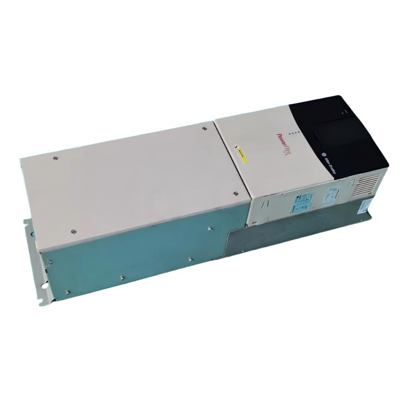
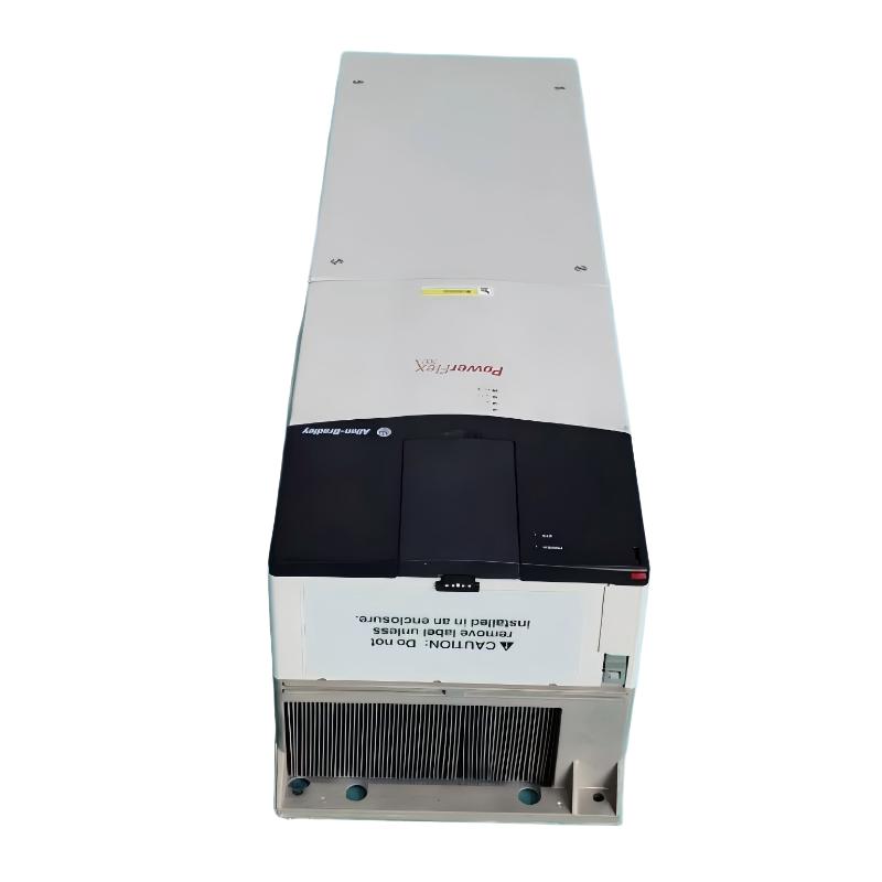
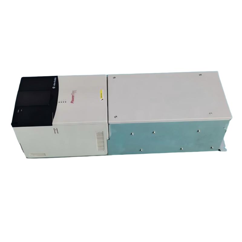
- Allen Bradley
- 20BF052A0ANNANC0
- PowerFlex AC Drive
- USA
- 1828.8 × 711.3 × 487.8 mm
- 229.07kg
- Xiamen, China
- New & In Stock
- T/T, PayPal, Western Union
- 1 Year
- 1-3 Working Days
- DHL, UPS, TNT, FedEx and EMS.
- 24-Hour Service
- COO
- 5
Our advantage

Global Logistics
We have a 10-year logistics and express cooperation agreement, so our products can be shipped to any place in the world.

Brand new and original
Our products are imported in bulk from the place of origin. Because of the cooperative relationship, our products are all original and 100% new.

24-hour service
We provide 7*24 hours service to our customers. We will be there whenever you need us.

Price advantage
All our products are priced very favorably because we have our own warehouse and supply.
| Company Information | |||
| [email protected] | |||
| Mobile | +8615980777398 | ||
| +8615980777398 | |||
| 15980777398 |
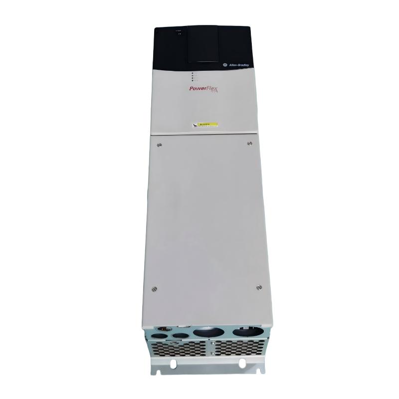
Allen-Bradley 20BF052A0ANNANC0 AC Drive — Product Specifications, Technical Overview, Applications, Advantages, and Related Models
1. Product Overview
The Allen-Bradley 20BF052A0ANNANC0 is a catalog number associated with the PowerFlex 700 series of industrial AC drives. This product family is designed to regulate AC motor operation in industrial machinery and automated production systems.
An AC drive adjusts the electrical output supplied to a compatible motor, allowing the motor to operate at different speeds according to process requirements. This can improve control over machine movement, support smoother acceleration and deceleration, and provide greater flexibility than fixed-speed operation.
Drives in this product category are commonly considered for conveyors, pumps, fans, mixers, material-handling equipment, and other motor-driven industrial systems. The suitability of this specific model depends on its nameplate ratings, installed options, and the requirements of the connected motor.
Technical note: The exact electrical ratings, physical dimensions, weight, and configuration associated with catalog number 20BF052A0ANNANC0 cannot be reliably established from the model number alone in this offline response. Unknown specifications are marked “Not confirmed” rather than replaced with estimates.
2. Basic Product Information
|
Parameter |
Specification |
|---|---|
|
Brand |
Allen-Bradley |
|
Model |
20BF052A0ANNANC0 |
|
Product family |
PowerFlex |
|
Product series |
PowerFlex 700 |
|
Product category |
Industrial AC variable-frequency drive |
|
Primary function |
AC motor speed control |
|
Additional function |
Motor control and process adjustment, depending on configuration |
|
Compatible motor type |
AC motor, subject to drive and motor compatibility |
|
Rated input voltage |
Not confirmed |
|
Input phase |
Not confirmed |
|
Rated input frequency |
Not confirmed |
|
Rated output current |
Not confirmed |
|
Motor power rating |
Not confirmed |
|
Horsepower rating |
Not confirmed |
|
Output frequency range |
Not confirmed |
|
Control interface |
Not confirmed |
|
Communication interface |
Not confirmed |
|
Operator interface |
Not confirmed |
|
Enclosure rating |
Not confirmed |
|
Cooling method |
Not confirmed |
|
Mounting arrangement |
Not confirmed |
|
Dimensions (H × W × D) |
Not confirmed |
|
Net weight |
Not confirmed kg |
|
Shipping weight |
Not confirmed kg |
|
Installation environment |
Industrial environment, subject to the actual unit’s specifications |
|
Intended use |
Variable-speed control of compatible motor-driven equipment |
3. Detailed Electrical Specifications
Electrical ratings are among the most important factors when selecting an industrial drive. The incoming supply, output current, motor power, and overload capability must all match the application.
|
Electrical Parameter |
Specification |
|---|---|
|
Model |
20BF052A0ANNANC0 |
|
Input voltage class |
Not confirmed |
|
Permissible input voltage range |
Not confirmed |
|
Input phase configuration |
Not confirmed |
|
Input frequency |
Not confirmed |
|
Rated input current |
Not confirmed |
|
Rated output voltage |
Not confirmed |
|
Rated output current |
Not confirmed |
|
Continuous output current |
Not confirmed |
|
Rated motor power |
Not confirmed |
|
Rated horsepower |
Not confirmed |
|
Output frequency range |
Not confirmed |
|
Overload capacity |
Not confirmed |
|
Power factor |
Not confirmed |
|
Efficiency |
Not confirmed |
|
Switching frequency |
Not confirmed |
|
Short-circuit current rating |
Not confirmed |
|
Grounding requirements |
Must be established from the exact installation specifications |
|
Branch-circuit protection |
Must be selected according to the verified ratings and applicable electrical requirements |
|
Motor cable requirements |
Depend on cable length, motor characteristics, installation conditions, and drive specifications |
|
Braking resistor compatibility |
Not confirmed |
|
Regenerative operation |
Not confirmed |
|
Line reactor requirements |
Application-dependent |
|
EMC filtering requirements |
Application- and installation-dependent |
3.1 Input Power
The drive must be connected to a supply that matches its rated input voltage and phase configuration.
Before installation, verify the nameplate information and the required upstream protection. Incorrect supply voltage or unsuitable protective devices can cause equipment damage and create an electrical hazard.
The supply circuit should also be designed around the installation’s fault-current conditions, grounding arrangement, and applicable electrical codes.
3.2 Output and Motor Compatibility
The drive’s output current rating must be sufficient for the connected motor under the intended operating conditions.
Motor selection should take account of the rated current on the motor nameplate, load torque, starting requirements, operating speed, and expected duty cycle. Horsepower alone is not enough to establish compatibility.
For equipment that starts under heavy load or experiences frequent changes in torque, the drive’s overload capability is particularly important.
3.3 Braking Requirements
Some machines need controlled stopping because of high inertia, frequent stops, or the risk of material movement after power commands are removed.
The required braking arrangement depends on the load and the drive’s actual configuration. A standard deceleration ramp should not be assumed to provide the braking performance required by every machine.
Before choosing braking accessories, confirm the drive’s supported braking arrangement and the machine’s stopping requirements.
4. Control and Functional Specifications
|
Control Parameter |
Specification |
|---|---|
|
Model |
20BF052A0ANNANC0 |
|
Motor-speed regulation |
Variable-speed operation, subject to configuration |
|
Torque-control functions |
Not confirmed for the exact catalog number |
|
Acceleration settings |
Configuration-dependent |
|
Deceleration settings |
Configuration-dependent |
|
Local operation |
Depends on the installed operator interface |
|
Remote operation |
Depends on the control wiring and available interfaces |
|
Digital inputs |
Quantity and electrical characteristics not confirmed |
|
Digital outputs |
Quantity and electrical characteristics not confirmed |
|
Analog inputs |
Quantity and supported signals not confirmed |
|
Analog outputs |
Quantity and supported signals not confirmed |
|
PLC integration |
Depends on available interfaces and installed options |
|
Network communication |
Not confirmed |
|
Preset-speed functions |
Requires configuration verification |
|
PID process control |
Requires configuration verification |
|
Fault and status monitoring |
Depends on the actual configuration |
|
Motor overload protection |
Exact implementation not confirmed |
|
Overcurrent protection |
Exact response and thresholds not confirmed |
|
Overvoltage protection |
Exact response and thresholds not confirmed |
|
Undervoltage protection |
Exact response and thresholds not confirmed |
|
Encoder feedback |
Not confirmed |
|
Parameter backup |
Requires a compatible tool and correct configuration information |
|
Safety functions |
Not confirmed; separate safety provisions may be required |
4.1 Speed Control
The principal function of an AC drive is to vary the operating speed of a compatible motor. The required speed can be determined by local commands, external control signals, or an automation system, depending on the installed configuration.
Adjustable speed can be useful when the machine needs different operating rates during startup, production, transfer, or shutdown.
4.2 Automation Integration
An industrial drive can form part of a larger control system containing a PLC, operator panel, sensors, switches, and motor-driven equipment.
The exact communication options and I/O configuration for 20BF052A0ANNANC0 have not been confirmed. Any design that depends on a particular network, control voltage, or signal type should be checked against the actual unit.
4.3 Fault Monitoring
Drive status and fault information can help maintenance personnel identify abnormal operating conditions.
The available diagnostic functions depend on the installed configuration. Correct troubleshooting also requires the appropriate documentation, safe isolation procedures, and an understanding of the complete electrical system.
5. Mechanical Specifications, Dimensions, and Weight
Dimensions and weight are essential when planning a new installation or replacing an existing drive. A unit may meet the electrical requirements yet still be unsuitable for a cabinet because of its physical size, mounting arrangement, or cooling requirements.
|
Mechanical Parameter |
Specification |
|---|---|
|
Model |
20BF052A0ANNANC0 |
|
Frame size |
Not confirmed |
|
Overall height |
Not confirmed |
|
Overall width |
Not confirmed |
|
Overall depth |
Not confirmed |
|
Dimensions (H × W × D) |
Not confirmed |
|
Net weight |
Not confirmed kg |
|
Shipping weight |
Not confirmed kg |
|
Enclosure type |
Not confirmed |
|
Enclosure protection rating |
Not confirmed |
|
Cooling arrangement |
Not confirmed |
|
Mounting orientation |
Not confirmed |
|
Mounting-hole spacing |
Not confirmed |
|
Power-terminal position |
Not confirmed |
|
Control-terminal position |
Not confirmed |
|
Cable-entry arrangement |
Not confirmed |
|
Required ventilation clearance |
Not confirmed |
|
Cabinet space requirement |
Must be determined from the correct mechanical drawing |
|
Maintenance access |
Must allow safe inspection and servicing |
Dimensions and weight: The exact height, width, depth, and net weight of 20BF052A0ANNANC0 are not confirmed in this offline description. These values should be taken from the specific unit’s nameplate information or mechanical documentation.
Do not use the dimensions of a related PowerFlex model as a substitute. Different frame sizes and configurations can have different mounting holes, terminal locations, and ventilation requirements.
6. Product Introduction
6.1 Industrial AC Motor Control
The PowerFlex 700 product family is designed for industrial applications that require adjustable motor operation. Rather than operating continuously at a fixed speed, a compatible motor can be controlled to meet the requirements of the machine or process.
This approach is useful in manufacturing environments where operating speed changes with product type, material flow, production rate, or process conditions.
For example, a conveyor can operate at a lower speed during loading and at a higher speed during normal production. A pump can adjust its output to meet changing demand, provided the pump and process are suitable for variable-speed operation.
6.2 Flexible Operating Conditions
Industrial machines do not always operate under the same load. A motor may experience different torque requirements during startup, steady operation, and shutdown.
An appropriately selected and configured drive can help manage these operating changes. Acceleration and deceleration settings can be adjusted to suit the machine, provided the selected settings remain within the drive’s capabilities and the process’s safety requirements.
6.3 Integration into Industrial Equipment
A drive is normally installed as part of a complete electrical system. The system may include the incoming supply, branch-circuit protection, the drive, an AC motor, control wiring, and a local or remote operating interface.
Additional components may be required according to the application, including line reactors, filters, braking equipment, disconnect devices, communication modules, or other accessories.
The need for each component must be determined from the actual drive configuration and the installation requirements.
6.4 Suitability for Existing Machinery
For maintenance and replacement work, a drive’s exact catalog number is important because seemingly similar products may have different electrical ratings or installed options.
Before replacing an existing unit, compare the voltage, current, motor power, overload requirements, communication interfaces, control wiring, and mechanical dimensions.
A replacement should be considered compatible only after these requirements have been checked.
7. Main Applications

7.1 Conveyor Systems
Conveyors are widely used in production lines, warehouses, packaging facilities, and material-handling operations. Variable-speed control can help regulate product movement and coordinate the speed of connected equipment.
When selecting a drive for a conveyor, consider starting torque, belt inertia, loaded-start conditions, operating hours, and the required acceleration and stopping times.

7.2 Pumps and Fluid-Handling Equipment
A compatible pump motor can be operated at different speeds to meet changing flow or pressure requirements. In suitable systems, this can improve process flexibility and may reduce energy consumption when full-speed operation is unnecessary.
Pump curves, minimum flow, static head, fluid properties, and motor cooling must be considered before applying variable-speed control.

7.3 Fans and Ventilation Systems
Industrial fans may need different airflow levels during different operating conditions. A drive can help adjust fan speed to meet changing ventilation or process-air requirements.
The selected drive must be suitable for the fan motor, required speed range, duty cycle, and environmental conditions.

7.4 Mixers and Agitators
Mixing equipment can experience varying torque demands as materials are added or processed. Adjustable speed can support different stages of a production cycle.
The drive should be selected according to the starting load, material characteristics, operating duration, and any periods of sustained high torque.

7.5 General Manufacturing Machinery
Industrial machinery may use adjustable motor speed to control feed rates, material transfer, and production sequences.
Applications requiring precise synchronization, encoder feedback, or specialized safety functions need a separate review of the actual drive configuration and the complete automation system.
8. Product Advantages
8.1 Adjustable Motor Speed
A variable-frequency drive allows a compatible motor to operate at different speeds instead of remaining at a single fixed operating point.
This can help a machine accommodate changes in production rate, material flow, or process demand. It may also reduce the need for mechanical speed adjustments in applications designed for variable-speed operation.
8.2 Controlled Acceleration and Deceleration
Appropriate ramp settings can help reduce sudden changes in motor speed.
This can reduce mechanical shock in suitable applications and may help protect belts, couplings, gears, and connected equipment from unnecessary stress. The actual benefit depends on the mechanical system and the selected settings.
8.3 Potential Energy Savings
Energy savings may be possible when a motor can operate at a lower speed while still meeting process requirements.
This is particularly relevant to suitable fan and centrifugal pump applications. Savings depend on the load characteristics, operating schedule, process requirements, motor efficiency, and drive losses.
A drive should not be assumed to reduce energy consumption in every application.
8.4 Flexible Production Control
Adjustable speed can make it easier to adapt a machine to different products or production stages.
Where the application is designed for variable-speed operation, this flexibility can reduce the need for manual mechanical adjustments and support more consistent process control.
8.5 Integration with Automation
Depending on the actual configuration, an industrial drive can be integrated with external control signals or supported automation interfaces.
This can help coordinate motor operation with sensors, PLC commands, and other equipment. The communication capabilities of this specific model must be confirmed before they are included in a system design.
8.6 Diagnostic Assistance
Available drive status and fault information can help maintenance personnel investigate operating issues and identify conditions that require attention.
The information provided depends on the installed options and configuration. Safe troubleshooting procedures and suitable technical documentation remain essential.
8.7 Support for Industrial Operating Requirements
The PowerFlex 700 family is intended for industrial motor-control applications. When properly selected and installed, a compatible drive can form part of a motor-control system designed around the application’s electrical and mechanical requirements.
Actual performance and reliability depend on correct sizing, suitable environmental conditions, installation quality, configuration, and maintenance.
9. Brand and Product Series
|
Item |
Description |
|---|---|
|
Brand |
Allen-Bradley |
|
Product family |
PowerFlex |
|
Product series |
PowerFlex 700 |
|
Model |
20BF052A0ANNANC0 |
|
Product type |
Industrial AC drive |
|
Main function |
Variable-speed AC motor control |
|
Typical application areas |
Material handling, pumps, fans, mixers, and industrial machinery |
|
Installation type |
Industrial electrical cabinet or equipment installation, subject to the exact unit’s requirements |
|
Control integration |
Depends on the installed interfaces and options |
|
Exact power rating |
Not confirmed |
|
Exact voltage class |
Not confirmed |
|
Exact dimensions |
Not confirmed |
|
Exact weight |
Not confirmed kg |
|
Lifecycle status |
Not confirmed |
The PowerFlex 700 family is associated with industrial AC motor control. However, the family name alone does not establish the exact electrical ratings or options of an individual drive.
For procurement, maintenance, or replacement, the full catalog number and nameplate information should be used to confirm that the selected unit meets the application requirements.
10. Five Related Models for Comparison
The following models are related catalog numbers for preliminary comparison. Their exact ratings and compatibility with 20BF052A0ANNANC0 have not been verified in this offline response.
They should be treated as comparison candidates rather than confirmed direct replacements.
|
No. |
Model |
Product Series |
Input Voltage |
Output Current |
Motor Power |
Dimensions (H × W × D) |
Weight |
|---|---|---|---|---|---|---|---|
|
1 |
20BF052A0ANNANC0 |
PowerFlex 700 |
Not confirmed |
Not confirmed |
Not confirmed |
Not confirmed |
Not confirmed kg |
|
2 |
20BE062A0ANNANC0 |
PowerFlex 700 |
Not confirmed |
Not confirmed |
Not confirmed |
Not confirmed |
Not confirmed kg |
|
3 |
20BE077A0ANNANC0 |
PowerFlex 700 |
Not confirmed |
Not confirmed |
Not confirmed |
Not confirmed |
Not confirmed kg |
|
4 |
20BE099A0ANNANC0 |
PowerFlex 700 |
Not confirmed |
Not confirmed |
Not confirmed |
Not confirmed |
Not confirmed kg |
|
5 |
20BE125A0ANNAND0 |
PowerFlex 700 |
Not confirmed |
Not confirmed |
Not confirmed |
Not confirmed |
Not confirmed kg |
10.1 How to Compare These Models
Begin with the electrical supply requirements. The replacement must match the available supply voltage and phase configuration.
Next, compare output current and overload capability against the connected motor and the machine’s expected load. A model with a different current rating should not be substituted without checking the motor requirements and the intended duty cycle.
The control interface is equally important. Verify the available digital and analog I/O, operator interface, communication options, and any special control features required by the existing installation.
Finally, compare the mechanical drawings. Similar catalog numbers do not guarantee identical dimensions, terminal positions, cooling requirements, or mounting-hole locations.
None of the listed models should be considered a direct substitute until the electrical, control, and mechanical specifications have been confirmed.
11. Five Other Allen-Bradley Models Worth Considering
The models below are from other Allen-Bradley drive product families. They may be relevant when evaluating alternative drive solutions, particularly for applications with different power, space, or control requirements.
They are not confirmed replacements for 20BF052A0ANNANC0.
|
No. |
Model |
Product Series |
Product Category |
Voltage |
Current / Power |
Typical Application |
Dimensions (H × W × D) |
Weight |
|---|---|---|---|---|---|---|---|---|
|
1 |
25B-D024N104 |
PowerFlex 525 |
Compact AC drive |
Not confirmed |
Not confirmed |
General-purpose machinery |
Not confirmed |
Not confirmed kg |
|
2 |
25B-D017N104 |
PowerFlex 525 |
Compact AC drive |
Not confirmed |
Not confirmed |
Conveyors and process equipment |
Not confirmed |
Not confirmed kg |
|
3 |
25B-D010N104 |
PowerFlex 525 |
Compact AC drive |
Not confirmed |
Not confirmed |
Pumps, fans, and industrial machinery |
Not confirmed |
Not confirmed kg |
|
4 |
22B-D012N104 |
PowerFlex 40 |
Compact AC drive |
Not confirmed |
Not confirmed |
General industrial motor control |
Not confirmed |
Not confirmed kg |
|
5 |
22B-D017N104 |
PowerFlex 40 |
Compact AC drive |
Not confirmed |
Not confirmed |
Small-scale motor-driven machinery |
Not confirmed |
Not confirmed kg |
11.1 PowerFlex 525 Alternatives
The PowerFlex 525 family is associated with compact variable-frequency drive applications. Depending on the exact rating and configuration, a suitable model may be considered for conveyors, pumps, fans, packaging machinery, and general industrial equipment.
A compact drive may be attractive where cabinet space is limited or where a smaller motor-control solution is required. Nevertheless, selection must be based on the actual supply voltage, motor current, power rating, overload capability, and control requirements.
The models listed above should be evaluated individually. Their catalog numbers alone do not establish the required ratings or guarantee compatibility.
11.2 PowerFlex 40 Alternatives
The PowerFlex 40 family may be considered for appropriate general-purpose motor-control applications.
A drive from this family should only be selected when its electrical ratings and functional capabilities meet the machine’s requirements. A smaller drive is not an appropriate replacement merely because it comes from the same brand.
Changing product families may also require adjustments to the cabinet, wiring, PLC program, communication system, operating procedures, and maintenance documentation.
12. Installation and Maintenance Considerations
12.1 Verify the Complete Catalog Number
Confirm that the catalog number on the physical unit is exactly 20BF052A0ANNANC0.
Record the nameplate ratings and any installed options. This information is necessary for selecting accessories, confirming compatibility, and planning maintenance or replacement.
12.2 Confirm Electrical Compatibility
Verify the incoming supply voltage, phase configuration, rated output current, motor power, protective devices, and grounding arrangement.
The drive must be suitable for the connected motor and the expected load. Electrical installation should be carried out by qualified personnel using the appropriate safety procedures.
12.3 Check Control and Communication Requirements
Determine whether the machine uses local controls, remote start and stop commands, analog references, digital inputs, PLC communication, or other interfaces.
Confirm that the exact unit supports the required functions. Do not assume that a particular communication option or control module is installed unless it has been verified.
12.4 Confirm Physical Dimensions and Weight
Before ordering a replacement, obtain the mechanical drawing for the exact catalog number.
Check height, width, depth, mounting-hole spacing, terminal access, cable clearance, and ventilation requirements. Confirm the net weight in kilograms so that the mounting arrangement and cabinet structure can support the equipment safely.
12.5 Review Cooling and Environmental Conditions
Verify the allowable ambient temperature, enclosure rating, cooling requirements, and required clearances.
Insufficient ventilation or unsuitable environmental conditions can reduce equipment reliability. Dust, moisture, contamination, and high temperatures should be considered during cabinet design.
12.6 Commission the Installation
Before returning the equipment to service, verify wiring, motor nameplate data, parameter settings, protective functions, and control signals.
Conduct the initial operating tests under controlled conditions. Check rotation direction, acceleration, deceleration, and response to operating commands before resuming normal production.
13. Pre-Purchase Verification Checklist
Use the following checklist before purchasing, replacing, or installing the drive.
Drive selection checklist
0 of 13 completed
14. Final Summary
The Allen-Bradley 20BF052A0ANNANC0 is associated with the PowerFlex 700 industrial AC drive family. Its general purpose is to provide adjustable motor operation for compatible industrial machinery and process equipment.
Potential application areas include conveyors, pumps, fans, mixers, and manufacturing machinery. Depending on the exact configuration and the requirements of the machine, a suitable drive can provide adjustable speed, controlled acceleration and deceleration, and integration with industrial control systems.
The exact input voltage, output current, motor power, control interfaces, dimensions, and weight of this catalog number remain Not confirmed in this offline description. The related and alternative models listed above are comparison candidates, not verified equivalents.
For a reliable purchasing or replacement decision, confirm the physical unit’s nameplate and the correct technical drawings. In particular, establish the electrical ratings, dimensions in height × width × depth, and net weight in kilograms before finalizing the installation or selecting a substitute.