

ProductPRODUCT
Featured products
Contact Us
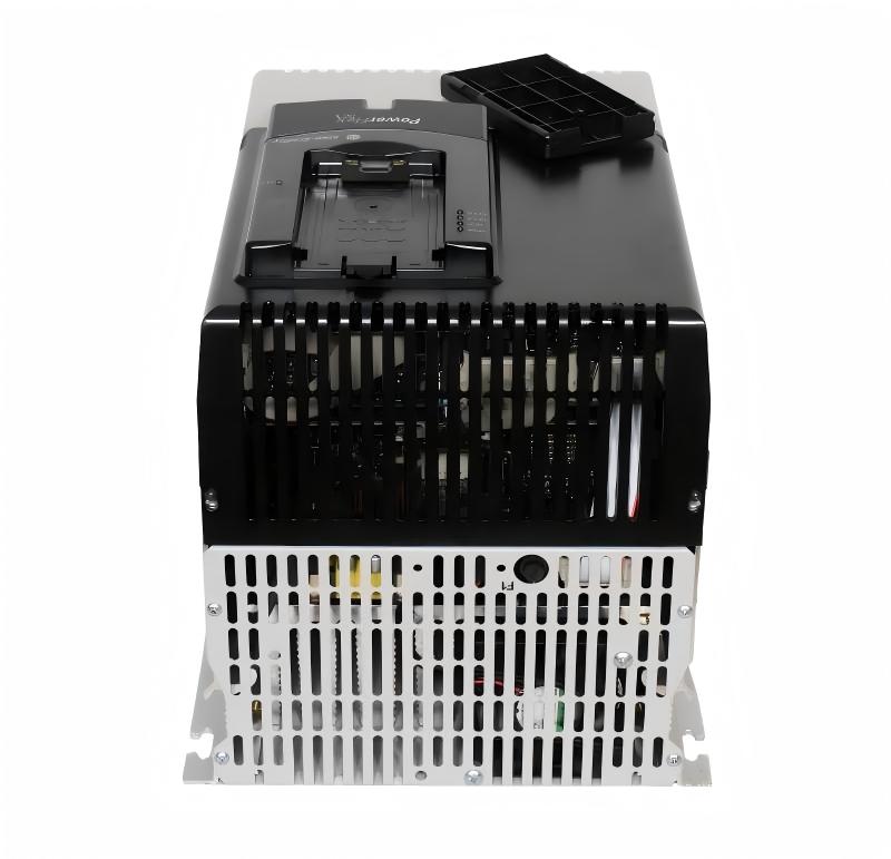
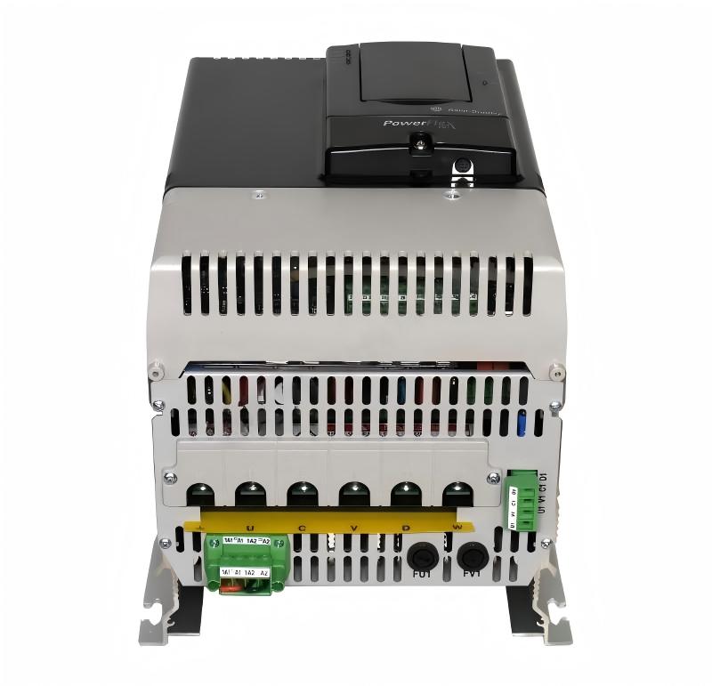
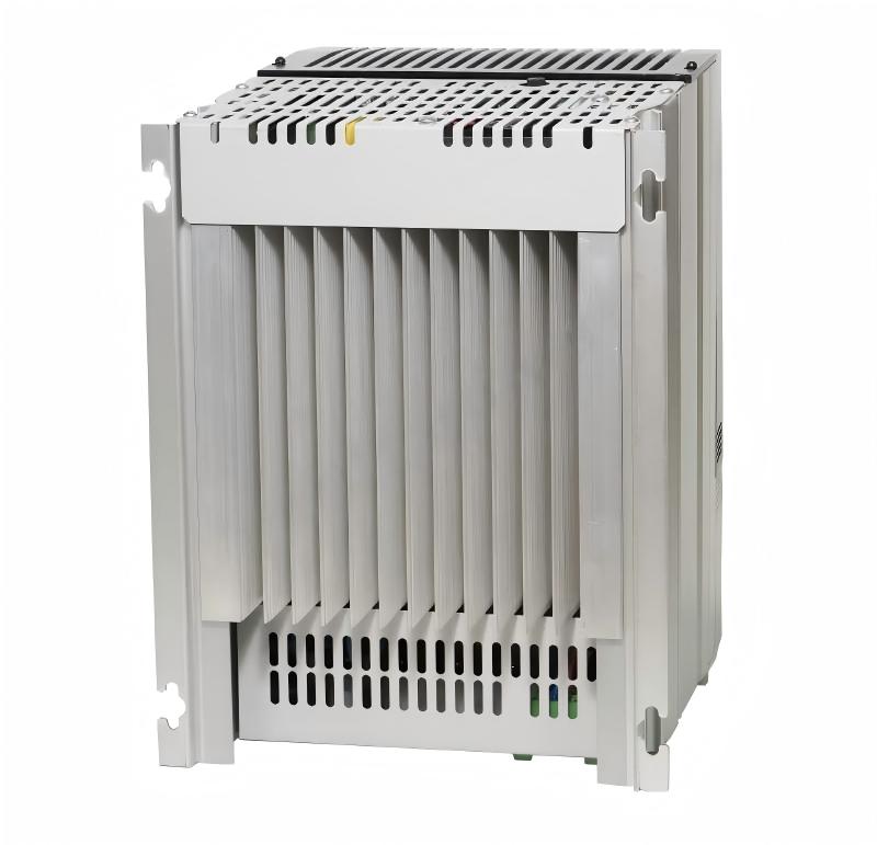
- Allen Bradley
- 21AD011A3AYNAEC0NNNN-ND-B0-C1-P1
- PowerFlex 70 AC SERIES A DRIVE
- USA
- 300 × 180 × 138 mm
- 6.89kg
- Xiamen, China
- New & In Stock
- T/T, PayPal, Western Union
- 1 Year
- 1-3 Working Days
- DHL, UPS, TNT, FedEx and EMS.
- 24-Hour Service
- COO
- 5
Our advantage

Global Logistics
We have a 10-year logistics and express cooperation agreement, so our products can be shipped to any place in the world.

Brand new and original
Our products are imported in bulk from the place of origin. Because of the cooperative relationship, our products are all original and 100% new.

24-hour service
We provide 7*24 hours service to our customers. We will be there whenever you need us.

Price advantage
All our products are priced very favorably because we have our own warehouse and supply.
| Company Information | |||
| [email protected] | |||
| Mobile | +8615980777398 | ||
| +8615980777398 | |||
| 15980777398 |
1. Product Overview
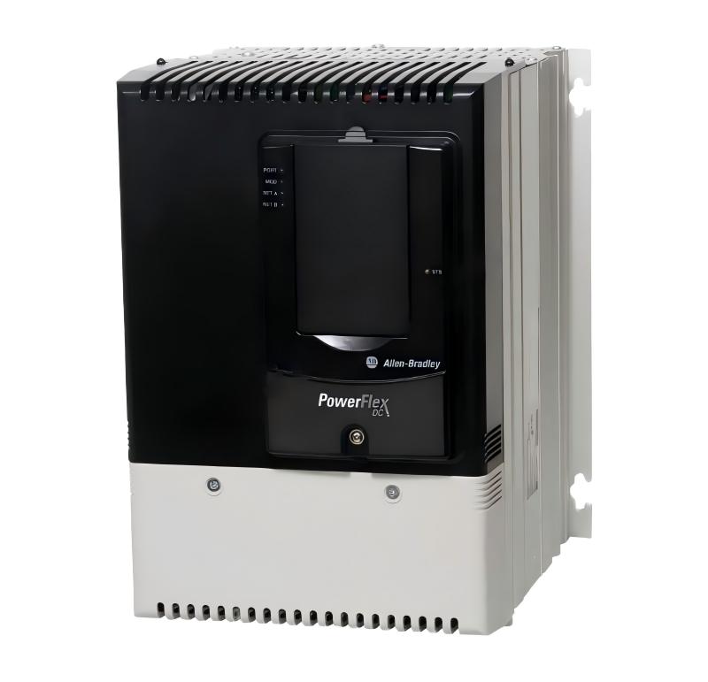
The Allen-Bradley 21AD011A3AYNAEC0NNNN-ND-B0-C1-P1 is a configured PowerFlex 70 AC drive designed for industrial motor speed control, acceleration, deceleration, torque management, and process automation.
This catalog number belongs to the PowerFlex 70 Configured Drives family and represents a factory-configured version rather than simply a basic standalone drive. The configuration combines the drive itself with specific control, braking, feedback, bypass, control-power, and power-input options.
The drive is rated for 480 VAC, three-phase input and provides an 11 A output rating. In the standard normal-duty rating, this corresponds to approximately 7.5 HP, while the heavy-duty rating is approximately 5 HP.
The particular configuration specified by 21AD011A3AYNAEC0NNNN-ND-B0-C1-P1 is a normal-duty, IP20/NEMA/UL Type 1 style configured drive with no bypass, drive-only control power, and no input protection supplied as part of the configured package.
The product is therefore well suited to industrial machinery where a compact variable-frequency AC drive is required for controlling standard three-phase induction motors.
2. Brand and Product Series
| Item | Description |
|---|---|
| Brand | Allen-Bradley |
| Product Family | PowerFlex |
| Product Series | PowerFlex 70 |
| Configured Drive Family | PowerFlex 70 Configured Drives |
| Catalog Number | 21AD011A3AYNAEC0NNNN-ND-B0-C1-P1 |
| Drive Type | Adjustable Frequency AC Drive |
| Motor Control | Variable-frequency motor control |
| Input | 480 VAC, 3-phase |
| Normal-Duty Current | 11 A |
| Normal-Duty Power | 7.5 HP / approximately 5.5 kW |
| Heavy-Duty Power | 5 HP / approximately 4.0 kW |
| Enclosure Type | IP20 / NEMA Type 1 style |
| Frame Size | C |
| Feedback | No encoder feedback |
| Bypass | No bypass |
| Input Protection Option | P1 – no input protection |
| Control Power | C1 – drive-only control power |
| Brake | Brake IGBT configuration |
| Brake Resistor | No internal brake resistor |
| Communication | No communication module in the basic configuration |
| I/O | Enhanced 24 V DC I/O |
| Application Class | Industrial variable-speed AC motor control |
The PowerFlex 70 family was developed as a general-purpose industrial AC drive platform. Its configuration system allows the drive to be ordered with different voltage classes, current ratings, enclosure arrangements, control options, communications, feedback options, bypass arrangements, and power-distribution accessories.
3. Main Product Parameters
| Parameter | Specification |
|---|---|
| Model / Catalog Number | 21AD011A3AYNAEC0NNNN-ND-B0-C1-P1 |
| Brand | Allen-Bradley |
| Series | PowerFlex 70 |
| Product Type | Configured AC Drive |
| Input Voltage | 480 VAC |
| Input Phase | 3 Phase |
| Output Current | 11 A |
| Normal-Duty Motor Rating | 7.5 HP |
| Normal-Duty Motor Rating | Approximately 5.5 kW |
| Heavy-Duty Motor Rating | 5 HP |
| Heavy-Duty Motor Rating | Approximately 4.0 kW |
| Frequency | 50/60 Hz class |
| Drive Duty | Normal Duty |
| Enclosure | IP20 / NEMA Type 1 |
| Frame | C |
| Feedback | No encoder feedback |
| Brake IGBT | Included |
| Internal Brake Resistor | None |
| Bypass | No bypass |
| Control Power | Drive-only control power |
| Input Protection | None included under P1 |
| I/O Configuration | Enhanced 24 V DC |
| Communication Module | None in this configuration |
| HIM | Configuration dependent; catalog configuration does not indicate an externally specified communications module |
| Cooling | Integral forced-air cooling |
| Mounting | Panel / cabinet mounting |
| Dimensions, Approx. | 300 × 180 × 138 mm |
| Dimensions, Approx. in Inches | 11.81 × 7.08 × 5.42 in |
| Drive Weight, Approx. | 6.89 kg |
| Application | Industrial variable-speed motor control |
| Motor Type | Three-phase AC induction motor and compatible AC motor applications |
The 11 A rating is one of the key characteristics of this model. At 480 VAC, the drive occupies the PowerFlex 70 size class associated with approximately 7.5 HP normal-duty operation.
The drive can also be applied in heavier-duty operating conditions at a reduced horsepower rating. This distinction is important because drive selection should not be based only on motor horsepower. The actual motor current, acceleration requirements, load inertia, overload requirements, operating cycle, ambient conditions, and duty profile should also be considered.
4. Dimensions and Weight
The 21AD011 configuration is associated with the Frame C size for the 480 VAC, 11 A class.
The following mechanical information represents the standard PowerFlex 70 Frame C drive envelope. Configured-drive cabinets, door-mounted devices, reactors, disconnects, or other selected options can increase the overall system dimensions.
| Mechanical Parameter | Approximate Value |
|---|---|
| Model / Catalog Number | 21AD011A3AYNAEC0NNNN-ND-B0-C1-P1 |
| Frame Size | C |
| Height | 300 mm |
| Width | 180 mm |
| Depth | 138 mm |
| Height | 11.81 in |
| Width | 7.08 in |
| Depth | 5.42 in |
| Drive Weight | 6.89 kg |
| Approximate Weight in Pounds | 15.2 lb |
| Mounting Style | Panel / cabinet mounting |
| Enclosure Class | IP20 / NEMA Type 1 style |
For cabinet design, sufficient clearance should be provided around the drive for airflow, wiring access, inspection, maintenance, and removal of the unit.
The physical dimensions of the drive itself should not be confused with the final dimensions of a configured system. A factory-configured PowerFlex 70 package can include additional components such as contactors, reactors, disconnect equipment, operator controls, or other accessories depending on the catalog configuration.
5. Understanding the Catalog Number
The long catalog number provides useful information about the construction and configuration of the product.
21AD011A3AYNAEC0NNNN-ND-B0-C1-P1
The principal sections can be interpreted as follows.
| Catalog Section | Meaning |
|---|---|
| 21A | PowerFlex 70 configured-drive family |
| D | 480 VAC class |
| 011 | 11 A drive rating |
| A | Basic configured-drive enclosure/control arrangement |
| 3 | Configuration identifier associated with the 480 V class |
| A | LCD/HIM-related base configuration code |
| Y | Brake IGBT installed |
| N | No internal brake resistor |
| A | Emission/filter configuration |
| E | Enhanced 24 V DC I/O |
| C0 | No encoder feedback |
| NNNN | Reserved / no special options |
| ND | Normal Duty |
| B0 | No bypass |
| C1 | Drive-only control power |
| P1 | No input protection |
This configuration approach is one of the distinguishing features of the configured-drive version of the PowerFlex 70 family.
Rather than purchasing a basic inverter and separately assembling every auxiliary component, the catalog structure allows the required configuration to be specified at the time of ordering.
6. Product Introduction
The Allen-Bradley 21AD011A3AYNAEC0NNNN-ND-B0-C1-P1 is an industrial variable-frequency AC drive intended to regulate the speed and operating behavior of three-phase AC motors.
Instead of operating a motor directly from a fixed-frequency AC supply, the drive controls the electrical frequency and voltage supplied to the motor. This allows the motor speed to be adjusted to suit the process.
For example, a conveyor does not always need to run at maximum speed. A fan may need to operate at different airflow levels. A pump may need to respond to changing process demand. A machine tool may require controlled acceleration and deceleration.
The drive provides the electronic interface between the incoming AC power supply and the motor.
The PowerFlex 70 platform is designed around this type of industrial motor-control requirement. It combines power conversion, motor-control functions, protection functions, parameter configuration, and control I/O within one industrial drive platform.
7. Normal-Duty 7.5 HP Rating
The 11 A rating corresponds to a 7.5 HP normal-duty application at the applicable 480 VAC input class.
This makes the drive appropriate for a broad range of small and medium industrial machines.
Typical motor sizes in this range are commonly found in conveyors, pumps, fans, blowers, mixers, machine tools, packaging equipment, material-handling systems, and process machinery.
The 7.5 HP rating should not be interpreted as an automatic indication that every 7.5 HP motor can be connected without further checking.
Motor full-load current is the more important selection parameter.
Two motors with the same horsepower rating can have different full-load current requirements depending on motor design, voltage, efficiency, power factor, speed, and manufacturer.
For this reason, the motor nameplate should always be checked before final drive selection.
8. Heavy-Duty Capability
The drive’s heavy-duty rating is approximately 5 HP.
The heavy-duty rating is useful for applications where the motor experiences greater overload requirements or where the load is more demanding during acceleration or operation.
Examples include machinery with higher starting torque, frequent acceleration and deceleration, intermittent heavy loading, or higher mechanical inertia.
The normal-duty and heavy-duty ratings should therefore be viewed as two different operating envelopes rather than simply two different horsepower numbers.
A machine that appears to require only 5 HP may need a drive selected according to the heavy-duty current rating if the operating cycle requires greater overload capability.
9. Brake IGBT Configuration
The catalog configuration includes a brake IGBT.
An internal braking transistor allows an external dynamic-braking resistor arrangement to be used when the application requires faster deceleration or controlled dissipation of regenerated energy.
This is particularly useful when a motor-driven load has significant inertia.
During deceleration, the motor can temporarily return electrical energy toward the drive’s DC bus. If that energy cannot be absorbed elsewhere, DC-bus voltage can rise.
A dynamic braking system provides a controlled path for handling this energy.
The catalog configuration does not include an internal brake resistor, so the braking resistor arrangement must be evaluated separately according to the actual application.
10. No Bypass Configuration
The B0 portion of the catalog number indicates a no-bypass configuration.
This means the configured drive is intended to provide the motor-control function without an integrated automatic or manual bypass arrangement.
For many machines this is exactly what is required.
A no-bypass configuration can simplify the overall architecture when the motor is intended to remain under VFD control during normal operation.
If a future application requires bypass operation, a different configured-drive option set may be necessary.
11. C1 Drive-Only Control Power
The C1 option indicates drive-only control power.
This configuration is suitable when the drive itself is the primary controlled device and the system does not require the larger control-power architecture associated with additional bypass equipment.
This can simplify panel wiring.
It is also important when reviewing the electrical design because control-power requirements should be considered separately from the main three-phase motor power circuit.
12. P1 No Input Protection
The P1 option means that input protection is not included in the configured package.
This is an important point when designing the electrical installation.
The upstream electrical system must provide the required branch-circuit protection and disconnecting means in accordance with the applicable installation requirements.
The P1 configuration should therefore be viewed as a drive package without integrated input fuses or an integrated drive input breaker.
This can be useful in installations where the customer or panel builder already has a standardized upstream protection system.
13. Enhanced 24 V DC I/O
The configuration uses enhanced 24 V DC I/O.
This provides a practical interface between the drive and the machine-control system.
Typical signals in an industrial installation can include run commands, stop commands, speed references, fault signals, status information, and other machine-control functions.
The drive can therefore be integrated into a larger control architecture without requiring every motor command to be generated locally at the drive.
14. No Encoder Feedback
The specified catalog configuration uses the no-feedback option.
This means an encoder is not included as part of the drive configuration.
For many general-purpose motor applications, sensorless control is sufficient.
Examples include ordinary conveyors, centrifugal pumps, fans, blowers, and many material-handling systems.
Applications that require extremely precise shaft positioning, tight speed regulation at very low speed, or closed-loop motion performance may require a different feedback configuration or a different drive family.
15. IP20 / NEMA Type 1 Construction
The drive is associated with an IP20 / NEMA Type 1 enclosure arrangement.
This type of drive is intended primarily for installation inside a suitable electrical enclosure or controlled industrial environment.
It is not intended to be treated as a fully sealed outdoor motor controller.
A properly designed cabinet should therefore provide suitable environmental protection against dust, moisture, conductive contamination, excessive humidity, and other site-specific hazards.
The cabinet should also provide adequate ventilation and thermal management.
16. Main Applications
Conveyor Systems
The drive is well suited to conveyor systems where motor speed needs to be adjusted according to production requirements.
Conveyors often benefit from controlled acceleration because an abrupt motor start can create mechanical shock, belt tension, product movement, or unnecessary stress on couplings and gearboxes.
With a variable-frequency drive, the conveyor can ramp smoothly to operating speed.
Speed control is also useful when the production rate changes.
For example, a packaging line may require one conveyor to operate at a different speed from another conveyor. The drive allows the motor speed to be adjusted without mechanically changing pulleys or gear ratios.
Pumps
The PowerFlex 70 platform can be used for many industrial pump applications.
Pump speed control can be useful when process demand changes throughout the production cycle.
Rather than running a motor continuously at full speed and controlling flow through mechanical throttling, the drive can vary motor speed.
This can provide more flexible process control.
Typical applications include process pumps, circulation pumps, water-handling systems, cooling systems, and industrial fluid-transfer equipment.
The actual pump control strategy should be selected according to pump type and process requirements.
Fans and Blowers
Fans and blowers are another common variable-speed application.
Airflow requirements can vary substantially during a production process.
A variable-speed drive allows the motor to operate at a speed appropriate for the required airflow.
This can also reduce unnecessary mechanical operation when the process does not require maximum airflow.
The drive can therefore be used in industrial ventilation, process-air systems, dust-collection equipment, exhaust systems, and other fan-based applications.
Packaging Machinery
Packaging machinery often requires controlled acceleration and deceleration.
Motors may operate conveyors, rollers, feeders, indexing mechanisms, or other machine elements.
A drive in the PowerFlex 70 family can provide adjustable speed and controlled ramping for these applications.
Where several motors operate together, the drive can also form part of a larger coordinated machine-control system.
Material Handling
Material-handling equipment often operates at different speeds depending on product type, production rate, or machine state.
The 21AD011 drive can provide the variable-speed motor control needed for many material-handling systems.
Examples include roller conveyors, transfer mechanisms, feeders, sorting equipment, and other electrically driven material-transfer machinery.
Mixers
Industrial mixers can require controlled motor starting and adjustable operating speed.
The drive can provide a gradual acceleration profile instead of applying full motor voltage immediately.
This can reduce mechanical shock and improve control of the mixing process.
The actual drive rating should be checked carefully where the mixer has high starting torque or substantial product viscosity.
Machine Tools
The drive can also be applied to various industrial machine tools and auxiliary machinery.
Variable speed can be useful where different materials, tooling conditions, or process stages require different motor speeds.
The application should be evaluated carefully if the machine requires precise positioning, very low-speed torque, or closed-loop feedback.
Material Processing Equipment
Processing machines frequently use motors in the 5–10 HP range.
The PowerFlex 70 11 A class can therefore be used in many processing systems where adjustable motor speed is required.
Examples include rollers, feeders, small production lines, cutting equipment, winding-related auxiliary machinery, and material transport systems.
17. Main Product Advantages
1. Industrial Variable-Speed Control
The primary advantage of the drive is its ability to control motor speed electronically.
This allows machine builders to adapt motor operation to process requirements.
2. Flexible Industrial Configuration
The configured-drive catalog structure allows different electrical and mechanical options to be combined.
This is useful for machine builders who need a specific combination of control, protection, braking, bypass, feedback, and enclosure functions.
3. 480 VAC Three-Phase Compatibility
The 480 VAC three-phase configuration is appropriate for many industrial electrical systems.
This voltage class is commonly encountered in industrial plants and machine installations.
4. 11 A Output Rating
The 11 A rating places the unit in a useful motor-power range for many industrial machines.
It is large enough for many production machines while remaining physically compact compared with higher-power drive frames.
5. Dynamic Braking Capability
The installed brake IGBT provides a convenient architecture for dynamic braking when the application requires controlled deceleration.
This can be particularly useful for loads with significant inertia.
6. Enhanced 24 V DC I/O
The enhanced 24 V DC I/O arrangement provides a practical interface for machine-control systems.
It can be used with industrial control circuits that employ 24 V DC signaling.
7. Compact Frame C Construction
The Frame C design provides a relatively compact physical package for an 11 A, 480 VAC drive.
The approximate base-drive dimensions are only about 300 × 180 × 138 mm.
This makes cabinet planning easier than with substantially larger drive frames.
8. No-BYPASS Architecture
For machines that do not require bypass operation, the B0 configuration avoids unnecessary bypass hardware.
This can result in a simpler control architecture.
9. No Encoder Requirement for General Applications
The no-feedback configuration is suitable for many ordinary variable-speed applications.
This can simplify motor installation because an encoder does not have to be installed on the motor solely for basic speed-control operation.
10. Suitable for Retrofit Projects
The PowerFlex 70 platform can be useful in industrial retrofit situations where an older adjustable-speed system needs to be replaced while retaining existing motor and mechanical equipment.
Before replacement, voltage, current, motor type, enclosure requirements, braking, control wiring, feedback requirements, and communication architecture should all be checked.
18. Recommended Same-Series or Closely Related Models
The following models are useful comparison points within the PowerFlex 70 / PowerFlex 70 configured-drive family.
They should not automatically be treated as direct replacements because voltage, current, frame size, enclosure, option configuration, and duty rating must match the actual application.
| Model | Series | Input Class | Current | Normal-Duty Rating | Heavy-Duty Rating | Frame | Approx. Dimensions | Approx. Weight |
|---|---|---|---|---|---|---|---|---|
| 21AD011A3AYNAEC0NNNN-ND-B0-C1-P1 | PowerFlex 70 Configured | 480 VAC, 3-phase | 11 A | 7.5 HP / 5.5 kW | 5 HP / 4.0 kW | C | 300 × 180 × 138 mm | 6.89 kg |
| 21AD014G3AYNANC0NNNN-ND-B0-C1-L1-P1 | PowerFlex 70 Configured | 480 VAC class | 14 A | 10 HP | 7.5 HP | C | Approx. Frame C | Approx. 6.9 kg |
| 21AD022ACAYNAEC0NNNN-ND-B0-C1-P3 | PowerFlex 70 Configured | 480 VAC class | 22 A | 15 HP | 10 HP | D | Approx. Frame D | Approx. 9.0 kg |
| 21AD027A0AYNANC0NNNN-ND-B0-C1-P1 | PowerFlex 70 Configured | 480 VAC class | 27 A | 20 HP | 15 HP | D | Approx. Frame D | Approx. 9.0 kg |
| 21AD034A3AYNANC0NNNN-ND-B0-C1-P1 | PowerFlex 70 Configured | 480 VAC class | 34 A | 25 HP | 20 HP | D | Approx. Frame D | Approx. 9.0 kg |
| 21AD040E3AYNAEC0NNNN-ND-B0-C1-P1 | PowerFlex 70 Configured | 480 VAC class | 40 A | 30 HP | 25 HP | D | Approx. Frame D | Approx. 9.0 kg |
The exact dimensions and weight of a configured-drive package can change when additional cabinet-mounted or power-distribution options are added. The values above are therefore best used for preliminary model comparison rather than final cabinet fabrication.
19. Same-Series Model Comparison
The 11 A model is located toward the lower end of this group.
Moving upward in current rating increases the available motor-power range.
| Model | Output Current | Normal Duty | Heavy Duty | Typical Use |
|---|---|---|---|---|
| 21AD011A3AYNAEC0NNNN-ND-B0-C1-P1 | 11 A | 7.5 HP | 5 HP | Small/medium industrial machines |
| 21AD014G3AYNANC0NNNN-ND-B0-C1-L1-P1 | 14 A | 10 HP | 7.5 HP | Larger conveyors, pumps, fans |
| 21AD022ACAYNAEC0NNNN-ND-B0-C1-P3 | 22 A | 15 HP | 10 HP | Medium-duty machinery |
| 21AD027A0AYNANC0NNNN-ND-B0-C1-P1 | 27 A | 20 HP | 15 HP | Medium industrial equipment |
| 21AD034A3AYNANC0NNNN-ND-B0-C1-P1 | 34 A | 25 HP | 20 HP | Higher-power machinery |
| 21AD040E3AYNAEC0NNNN-ND-B0-C1-P1 | 40 A | 30 HP | 25 HP | Larger process machinery |
This comparison shows why the 21AD011 should not simply be replaced by a higher-current model without checking the motor and application.
A larger drive may provide more current capability, but the installation, protection, motor-cable sizing, cabinet thermal design, and control configuration may also change.
20. Five Popular Related Models Under the Same Brand
The following models are broader Allen-Bradley AC-drive products that are useful for comparison.
They belong to different PowerFlex families and therefore should be regarded as related products rather than direct replacements for the 21AD011 configured PowerFlex 70.
| Model | Product Family | Input / Current | Power Class | Key Features | Approx. Dimensions | Approx. Weight |
|---|---|---|---|---|---|---|
| 25B-D010N114 | PowerFlex 525 | 380–480 VAC, 3-phase, 10.5 A | 5 HP / 4 kW class | Compact drive, embedded EtherNet/IP, safety functions, integral keypad | 228.09 × 139.95 × 239.01 mm | 2.193 kg |
| 20AD011A3AYNANC0 | PowerFlex 70 | 480 VAC, 3-phase, 11 A | 7.5 HP | Standard PowerFlex 70 drive configuration | Approx. 300 × 180 × 138 mm | Approx. 6.89 kg |
| 20AD014A3AYNANC0 | PowerFlex 70 | 480 VAC, 3-phase, 14 A | 10 HP | Higher-current PowerFlex 70 | Approx. Frame C/D depending configuration | Approx. 9 kg class |
| 20F1ANE033JA0NNNNN | PowerFlex 753 | 480 VAC class | Application-dependent | Higher-end industrial AC drive platform | Configuration dependent | Configuration dependent |
| 20G11FD052AA0NNNNN | PowerFlex 755 | 480 VAC class | Higher-power class | Advanced industrial AC drive platform | Configuration dependent | Configuration dependent |
The PowerFlex 525 is particularly different from the 21AD011 because it is a much newer compact drive architecture with integrated networking and modern machine-control features.
The PowerFlex 753 and PowerFlex 755 families are positioned for more demanding industrial applications and provide substantially broader control and integration capabilities.
Therefore, these models should be considered when evaluating a new system rather than assuming that they are mechanically interchangeable with the PowerFlex 70.
21. PowerFlex 70 Versus PowerFlex 525
One of the most useful comparisons is between the PowerFlex 70 and PowerFlex 525.
| Feature | 21AD011 PowerFlex 70 | 25B-D010N114 PowerFlex 525 |
|---|---|---|
| Model | 21AD011A3AYNAEC0NNNN-ND-B0-C1-P1 | 25B-D010N114 |
| General Role | Configured industrial AC drive | Compact modern AC drive |
| Voltage | 480 VAC class | 380–480 VAC |
| Phases | 3-phase | 3-phase |
| Current | 11 A | 10.5 A |
| Power Class | 7.5 HP ND | 5 HP class |
| Feedback | No encoder in specified configuration | Application/configuration dependent |
| Communications | No communication module in specified configuration | Embedded EtherNet/IP |
| Keypad | Configuration dependent | Integral keypad |
| Safety | Legacy platform configuration | Integrated safety functions |
| Approx. Weight | 6.89 kg | 2.193 kg |
| Physical Size | Larger | Much more compact |
The PowerFlex 525 is much smaller and incorporates more modern integrated connectivity features.
The PowerFlex 70, however, has a long-established industrial architecture and is particularly relevant when maintaining an existing PowerFlex 70 installation or replacing a configured drive within an existing machine platform.
22. PowerFlex 70 Versus PowerFlex 753
The PowerFlex 753 is designed for more advanced industrial applications.
The comparison is therefore less about simple horsepower matching and more about system requirements.
| Characteristic | PowerFlex 70 | PowerFlex 753 |
|---|---|---|
| Typical Position | General industrial drive | Advanced industrial drive |
| Motor Control | Variable-frequency AC control | Advanced AC motor control |
| Application Complexity | General machine control | More demanding machine/process applications |
| Feedback | Optional depending configuration | Broad feedback capability |
| Networking | Optional modules | Extensive communication options |
| Control Architecture | Established drive platform | More advanced architecture |
| Typical Application | Conveyors, pumps, fans, machinery | Complex machinery, process systems, demanding automation |
| Replacement Relationship | Existing legacy platform | Modernization alternative, not a direct mechanical substitute |
23. PowerFlex 70 Versus PowerFlex 755
The PowerFlex 755 is generally considered when the application requires a broader range of control, feedback, networking, and system-integration capabilities.
| Feature | PowerFlex 70 | PowerFlex 755 |
|---|---|---|
| Product Generation | Earlier industrial AC-drive platform | Advanced industrial AC-drive platform |
| Typical Application | General industrial machinery | High-performance industrial machinery |
| Power Range | Small through larger drive sizes | Broad industrial power range |
| Feedback | Optional | Extensive feedback options |
| Communications | Optional modules | Extensive communication architecture |
| Motion/Positioning | Limited compared with modern platforms | More extensive |
| Integration | Conventional industrial control | Advanced automation integration |
| Typical Reason to Select | Existing system compatibility | New or upgraded high-performance system |
24. Application Selection Guide
The following table provides a practical way to think about the 21AD011.
| Application | Suitability | Important Consideration |
|---|---|---|
| Conveyor | Very suitable | Check acceleration and load inertia |
| Small pump | Suitable | Check pump type and motor current |
| Fan | Suitable | Check required speed range |
| Blower | Suitable | Check starting torque |
| Packaging machine | Suitable | Check acceleration/deceleration cycle |
| Mixer | Application dependent | Check starting torque and overload |
| Machine tool | Application dependent | Feedback may be required |
| High-inertia machine | Suitable with correct braking design | Evaluate dynamic braking |
| Precision positioning | Limited | Consider advanced drive/motion platform |
| Simple variable-speed motor | Very suitable | Verify motor nameplate current |
| Retrofit | Suitable | Check existing wiring and control architecture |
| Outdoor installation | Not as a bare drive | Requires suitable enclosure |
| Washdown environment | Not as a bare IP20 drive | Use appropriate enclosure/protection |
25. Installation Considerations
The 21AD011 should be installed in an electrical cabinet or enclosure appropriate for the environment.
The cabinet should provide sufficient ventilation.
Variable-frequency drives generate heat during operation. Although the drive is relatively compact, the thermal output must still be considered when several drives or other heat-producing components are installed inside the same enclosure.
The drive should not be mounted immediately next to another heat-generating device without considering airflow.
Cable routing is also important.
Motor output cables should be routed separately from sensitive low-level control wiring where practical.
Grounding should be designed correctly for the drive, motor, cabinet, and associated control system.
26. Motor Compatibility
Before selecting this drive for a particular motor, the motor nameplate should be checked.
Important information includes:
- Motor voltage
- Motor full-load current
- Motor horsepower
- Motor frequency
- Motor speed
- Motor service factor
- Motor insulation system
- Motor duty cycle
- Motor connection configuration
The most important comparison is generally the motor full-load current versus the drive’s applicable output-current rating.
A motor labeled 7.5 HP is not automatically suitable merely because the drive is also labeled 7.5 HP.
The actual motor current must remain within the drive’s applicable operating limits.
27. Dynamic Braking Application
Dynamic braking deserves special attention with this model because the configuration includes the brake IGBT.
A high-inertia load can continue rotating after the drive commands deceleration.
The motor then acts as a generator and sends energy back toward the drive.
The resulting DC-bus energy can increase bus voltage.
A correctly selected braking resistor can dissipate this energy.
Typical applications that may require braking consideration include:
- High-inertia conveyors
- Centrifuges
- Roll systems
- Certain winding machines
- Material-handling equipment
- Rapid-stop machinery
- Machines with frequent acceleration and deceleration
The braking resistor must be selected according to the actual braking energy and duty cycle.
28. Why the Frame Size Matters
Frame size is not simply a physical designation.
It also provides information about the drive’s power-conversion hardware and mechanical package.
The 21AD011 is associated with the PowerFlex 70 Frame C class.
This gives the drive a useful balance between power capacity and physical size.
For a cabinet designer, knowing the frame is important because mounting holes, clearance requirements, cable-entry arrangements, heat dissipation, and overall enclosure design depend on the physical frame.
29. Maintenance Considerations
Routine maintenance should include inspection of the cabinet environment, cooling path, ventilation openings, electrical connections, and signs of contamination.
Dust accumulation can reduce cooling efficiency.
Loose power connections can create excessive heating.
High cabinet temperatures can reduce the service life of electronic components.
Where the drive operates continuously, preventive maintenance is particularly important.
The surrounding cabinet should also be checked because many apparent drive problems are actually caused by external conditions such as inadequate cooling, poor grounding, unstable incoming power, damaged motor cables, or motor insulation problems.
30. Retrofit Considerations
The 21AD011 is especially relevant when dealing with existing PowerFlex 70 installations.
A retrofit evaluation should compare:
| Check Item | What to Verify |
|---|---|
| Input Voltage | Existing supply must match drive voltage class |
| Motor Current | Motor full-load current must be compatible |
| Motor Power | Compare actual motor rating with ND/HD rating |
| Feedback | Determine whether encoder feedback is required |
| Braking | Determine whether dynamic braking is required |
| Control Voltage | Verify 24 V DC I/O requirements |
| Communications | Check PLC/HMI/network architecture |
| Cabinet | Verify physical dimensions and thermal capacity |
| Protection | Provide appropriate upstream protection |
| Grounding | Verify protective and control grounding |
| Motor Cable | Check cable rating and installation |
| Parameter Set | Review acceleration, deceleration, current, frequency and motor data |
| Safety | Verify machine safety architecture independently |
31. Advantages for Machine Builders
For machine builders, the configured-drive format can be particularly useful.
Instead of treating the drive as a completely generic inverter, the catalog number specifies a defined combination of functions.
This can simplify procurement.
It can also make replacement identification easier because the original catalog number records the basic electrical and option configuration.
For machines manufactured in larger quantities, standardized drive configurations can help reduce variation between machine builds.
32. Advantages for Industrial Users
For industrial users, the main practical advantage is controlled motor operation.
The drive can help adapt motor speed to the process rather than forcing the motor to operate continuously at one fixed speed.
It can also provide controlled acceleration and deceleration.
This is valuable for mechanical systems where abrupt starts or stops can create stress.
The drive can also form part of a larger automation system through its I/O and optional communications architecture.
33. Important Difference Between 21AD011 and 20AD011
The two catalog families can look very similar because both use the PowerFlex 70 architecture.
The 21A designation refers to the configured-drive family, while 20A is used for the standard PowerFlex 70 drive catalog family.
| Characteristic | 21A Configured Drive | 20A Standard Drive |
|---|---|---|
| Catalog Family | 21AD011… | 20AD011… |
| Product | PowerFlex 70 Configured | PowerFlex 70 |
| Main Purpose | Factory-configured drive package | Standard drive |
| Options | Built into configured catalog number | Selected separately |
| Bypass Options | Available through configured catalog | Separate system/configuration |
| Control Power Options | Configurable | Standard/options |
| Input Protection | Configurable | System dependent |
| Cabinet Integration | More configuration-oriented | More standalone-oriented |
This distinction is important when purchasing a replacement.
A standard 20A drive may have similar electrical ratings but may not physically or functionally duplicate every option contained in a 21A configured drive.
34. Product Selection Checklist
Before selecting the 21AD011 for a project, check the following:
| Selection Item | Requirement |
|---|---|
| Input Voltage | 480 VAC, 3-phase class |
| Motor Current | Within applicable 11 A drive rating |
| Normal-Duty Motor | Up to approximately 7.5 HP |
| Heavy-Duty Motor | Up to approximately 5 HP |
| Motor Frequency | Compatible with application |
| Motor Type | Compatible three-phase AC motor |
| Enclosure | Suitable cabinet required |
| Environment | Clean, controlled industrial environment |
| Braking | Evaluate if rapid stopping is required |
| Feedback | No encoder in specified configuration |
| Communications | Additional communication solution may be required |
| Input Protection | Must be provided appropriately upstream |
| Cooling | Cabinet thermal design required |
| Mounting | Frame C mechanical envelope |
| Weight | Approximately 6.89 kg for the base drive |
| Control | Enhanced 24 V DC I/O |
| Bypass | None |
| Duty | Normal Duty |
35. Practical Example – Conveyor Application
Consider a conveyor equipped with a 7.5 HP, 480 VAC three-phase motor.
The conveyor operates continuously but needs to change speed during different production stages.
The 21AD011 provides an appropriate drive class for this type of application when the motor’s actual full-load current is within the drive rating.
During startup, the drive can accelerate the motor gradually.
Instead of applying full operating conditions instantly, the acceleration profile can be configured according to the mechanical characteristics of the conveyor.
During production, the speed reference can be adjusted according to production requirements.
During stopping, the drive can decelerate the conveyor according to the programmed deceleration profile.
If the conveyor has very high inertia or needs extremely fast stopping, the braking system must be evaluated separately.
36. Practical Example – Pump Application
For a 480 VAC industrial pump motor, the drive can regulate motor speed according to process demand.
At lower demand, the motor can operate below maximum speed.
At higher demand, the drive can increase the motor speed.
This provides a flexible method of controlling the motor without mechanically changing the transmission ratio.
The pump’s minimum and maximum operating speeds should be checked carefully.
Some pump types have minimum-speed requirements, and some process systems have specific flow or pressure constraints.
37. Practical Example – Fan Application
A 7.5 HP fan can operate at different speeds depending on ventilation requirements.
A variable-frequency drive can allow the motor to run at a reduced speed when full airflow is unnecessary.
This is one of the classic applications for AC variable-speed drives.
The drive can also provide a controlled acceleration sequence, reducing mechanical shock to the fan and motor assembly.
38. Practical Example – High-Inertia Machine
Suppose the drive operates a machine with a large rotating mass.
When the stop command is issued, the machine continues rotating because of inertia.
The drive must remove this stored mechanical energy.
If the required stopping time is short, the regenerated energy can become significant.
In this type of application, the installed brake IGBT becomes particularly useful because it allows a properly designed external braking resistor system to be incorporated.
The resistor size and duty cycle should be calculated from the actual machine characteristics.
39. Why the 21AD011 Is Useful as an Industrial Drive
The strength of this model is not simply its 11 A rating.
Its value comes from the combination of:
- 480 VAC three-phase operation
- 11 A output capacity
- 7.5 HP normal-duty rating
- 5 HP heavy-duty rating
- PowerFlex 70 architecture
- Configured-drive construction
- Frame C mechanical package
- Brake IGBT
- Enhanced 24 V DC I/O
- No-bypass configuration
- Drive-only control power
- No encoder requirement in the specified configuration
- Industrial cabinet-mount construction
These characteristics make it suitable for many conventional industrial motor-control systems.
40. Final Technical Summary
| Parameter | Final Specification |
|---|---|
| Brand | Allen-Bradley |
| Series | PowerFlex 70 |
| Product Type | Configured AC Drive |
| Catalog Number | 21AD011A3AYNAEC0NNNN-ND-B0-C1-P1 |
| Input Voltage | 480 VAC |
| Input | 3-phase |
| Output Current | 11 A |
| Normal Duty | 7.5 HP / approximately 5.5 kW |
| Heavy Duty | 5 HP / approximately 4.0 kW |
| Frame | C |
| Enclosure | IP20 / NEMA Type 1 |
| Brake IGBT | Yes |
| Internal Brake Resistor | No |
| Feedback | No encoder feedback |
| I/O | Enhanced 24 V DC |
| Bypass | No bypass |
| Control Power | Drive-only control power |
| Input Protection | P1 – no input protection |
| Communications | No communication module in specified configuration |
| Approx. Height | 300 mm |
| Approx. Width | 180 mm |
| Approx. Depth | 138 mm |
| Approx. Dimensions | 300 × 180 × 138 mm |
| Approx. Weight | 6.89 kg |
| Primary Application | Industrial variable-speed AC motor control |
| Typical Machines | Conveyors, pumps, fans, blowers, packaging machinery, material handling and general industrial equipment |
41. Recommended Model List at a Glance
Same Series / Closely Related
| Model | Current | Normal Duty | Heavy Duty | Frame / Class |
|---|---|---|---|---|
| 21AD011A3AYNAEC0NNNN-ND-B0-C1-P1 | 11 A | 7.5 HP | 5 HP | C |
| 21AD014G3AYNANC0NNNN-ND-B0-C1-L1-P1 | 14 A | 10 HP | 7.5 HP | C |
| 21AD022ACAYNAEC0NNNN-ND-B0-C1-P3 | 22 A | 15 HP | 10 HP | D |
| 21AD027A0AYNANC0NNNN-ND-B0-C1-P1 | 27 A | 20 HP | 15 HP | D |
| 21AD034A3AYNANC0NNNN-ND-B0-C1-P1 | 34 A | 25 HP | 20 HP | D |
| 21AD040E3AYNAEC0NNNN-ND-B0-C1-P1 | 40 A | 30 HP | 25 HP | D |
Same Brand – Popular / Related PowerFlex Models
| Model | Series | Main Rating / Class | Approx. Dimensions | Approx. Weight |
|---|---|---|---|---|
| 25B-D010N114 | PowerFlex 525 | 380–480 VAC, 10.5 A, 5 HP / 4 kW class | 228.09 × 139.95 × 239.01 mm | 2.193 kg |
| 20AD011A3AYNANC0 | PowerFlex 70 | 480 VAC, 11 A, 7.5 HP | Approx. 300 × 180 × 138 mm | Approx. 6.89 kg |
| 20AD014A3AYNANC0 | PowerFlex 70 | 480 VAC, 14 A, 10 HP | Approx. Frame C/D | Approx. 9 kg class |
| 20F1ANE033JA0NNNNN | PowerFlex 753 | Industrial AC drive | Configuration dependent | Configuration dependent |
| 20G11FD052AA0NNNNN | PowerFlex 755 | Industrial AC drive | Configuration dependent | Configuration dependent |
42. Overall Product Description
The Allen-Bradley 21AD011A3AYNAEC0NNNN-ND-B0-C1-P1 is a PowerFlex 70 configured 480 VAC three-phase AC drive rated at 11 A, with a normal-duty motor rating of approximately 7.5 HP and a heavy-duty rating of approximately 5 HP.
Its Frame C construction provides a relatively compact industrial package, with the standard drive envelope being approximately 300 × 180 × 138 mm and a drive weight of approximately 6.89 kg.
The configuration includes an integrated brake IGBT, enhanced 24 V DC I/O, no encoder feedback, no bypass, drive-only control power, and no integrated input protection under the P1 option.
The model is particularly appropriate for conventional industrial machinery requiring reliable variable-speed AC motor control rather than high-end motion or precision positioning.
Typical applications include conveyors, pumps, fans, blowers, packaging equipment, material-handling machinery, mixers, process equipment, and general-purpose industrial machines.
For replacement work, the full catalog number should be matched rather than comparing only the 11 A rating. The suffix options are important because they define the control-power arrangement, bypass configuration, input protection, feedback, I/O, braking, and other characteristics of the configured package.
The model should therefore be treated as a complete configured-drive catalog number rather than simply an 11 A inverter.