
NewsNEWCENTER
Featured products
Contact Us
Schneider 140ACI04000C Analog Input Module Troubleshooting Guide
2026-09-29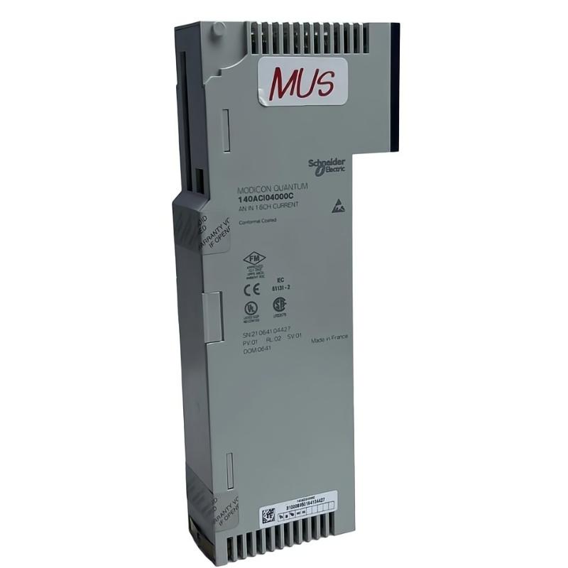
Schneider 140ACI04000C Analog Input Module troubleshooting should begin with the complete signal path rather than immediately replacing the module. When an analog value is missing, unstable, incorrect, or outside the expected operating range, technicians should systematically check the field instrument, wiring, module status, PLC configuration, scaling, grounding, and application logic. This approach helps distinguish a genuine 140ACI04000C hardware problem from an external wiring or configuration fault.
Understanding 140ACI04000C Analog Input Faults
An analog input problem can originate at several points in the measurement chain:
Field Instrument
      ↓
Signal Wiring
      ↓
140ACI04000C Input Channel
      ↓
Quantum I/O System
      ↓
PLC Data
      ↓
Scaling / Logic
      ↓
HMI / SCADA
A problem at any point can produce a similar symptom on the operator screen. For this reason, troubleshooting should move from the physical signal toward the software layer instead of assuming that the analog input module itself has failed.
Common Schneider 140ACI04000C Symptoms
- Analog value remains at zero or near the lower end.
- Input value does not change when the process changes.
- Reading is unstable or fluctuates unexpectedly.
- PLC value differs significantly from the field instrument.
- One input channel behaves differently from other channels.
- Several channels show abnormal values simultaneously.
- PLC configuration does not match the installed hardware.
- Module or rack diagnostics indicate an abnormal condition.
- HMI displays an incorrect engineering value.
Common Causes of 140ACI04000C Faults
Typical causes include incorrect field wiring, loose connectors, damaged instrumentation cable, incorrect signal configuration, grounding problems, electrical interference, incorrect PLC scaling, field transmitter problems, and module hardware failure.
| Symptom | Possible Cause | Initial Check |
|---|---|---|
| No input value | Open circuit, incorrect wiring, inactive transmitter | Check field signal and wiring |
| Constant value | Signal path interruption or software issue | Check field source and PLC variable |
| Fluctuating value | Noise, shielding, grounding, unstable source | Inspect cable routing and grounding |
| Incorrect magnitude | Scaling or configuration mismatch | Compare raw input and configured range |
| Multiple abnormal channels | Rack, power, common wiring, or configuration issue | Check system-level diagnostics |
140ACI04000C Diagnostic Flow
Abnormal Analog Reading
          ↓
Check PLC Diagnostic Status
          ↓
Is Module Recognized?
      ↙          ↘
    NO            YES
    ↓              ↓
Check Rack /    Check Field
Configuration   Signal
                   ↓
             Signal Present?
              ↙          ↘
            NO            YES
            ↓              ↓
       Check Wiring    Check PLC
       & Instrument    Configuration
                           ↓
                    Check Scaling
                           ↓
                    Check Grounding
                           ↓
                     Compare Channels
                           ↓
                    Suspect Hardware
                    Only if Evidence
                    Supports It
Step-by-Step Schneider 140ACI04000C Troubleshooting
1. Check the Module and Rack
Inspect the physical installation first. Confirm that the 140ACI04000C is correctly seated and that the rack does not show an abnormal condition. If several modules in the same rack are affected, investigate the rack, power, or system configuration before replacing an individual analog input module.
2. Check the Field Instrument
Confirm that the connected transmitter or sensor is operating correctly. If the field instrument itself is not generating the expected signal, replacing the 140ACI04000C will not correct the problem.
3. Check the Field Wiring
Inspect the signal conductors, connectors, terminal points, and cable insulation. Pay particular attention to loose terminals and incorrect returns. Compare the actual wiring with the applicable 140ACI04000C documentation rather than relying on memory.
4. Check Grounding and Shielding
Unexpected analog fluctuations are often associated with grounding or electromagnetic interference. Inspect the shield termination and cable route. Instrumentation wiring should not run unnecessarily alongside high-current switching circuits or motor cables.
5. Check PLC Configuration
Confirm that the PLC configuration corresponds to the installed hardware. Incorrect module selection, addressing, channel configuration, or data interpretation can make a healthy input appear faulty.
6. Check Scaling
If the raw input changes correctly but the engineering value shown by the PLC or HMI is wrong, investigate the scaling calculation before condemning the hardware.
A useful diagnostic concept is:
Physical Signal
      ↓
Module Input Data
      ↓
PLC Raw Value
      ↓
Scaling Calculation
      ↓
Engineering Value
      ↓
HMI Display
The first point at which the value becomes incorrect identifies the most useful area for further investigation.
Testing an Abnormal 140ACI04000C Channel
When one channel appears abnormal, compare it with a known-good channel where the application and field conditions allow a meaningful comparison. This can help determine whether the problem follows the field circuit or remains associated with the module channel.
- Record the abnormal PLC value.
- Record the corresponding field instrument condition.
- Check the physical wiring.
- Measure the field signal using an appropriate instrument.
- Compare the measured signal with the PLC input data.
- Check configuration and scaling.
- Inspect grounding and shielding.
- Compare with other functioning channels.
- Only then evaluate the possibility of module hardware failure.
Illustrative 140ACI04000C Diagnostic Record
The following is an example of a troubleshooting record for training purposes. The values are illustrative and should not be treated as universal specifications for the module.
Observed PLC Input:        Unstable
Field Instrument:          Stable
Field Wiring:              Verified
Cable Routing:             Near Power Conductors
Shielding:                 Inconsistent
PLC Configuration:         Correct

Initial Conclusion:
Investigate electromagnetic interference and grounding
before replacing the analog input module.

Corrective Action:
Improve signal cable routing and verify shielding.

Final Check:
PLC input becomes stable and follows process changes.
When to Suspect 140ACI04000C Hardware Failure
Hardware replacement should generally be considered only after external causes have been eliminated. Stronger evidence of a module problem may include persistent abnormal behavior on a properly wired input, correct field signal measurements, correct PLC configuration, normal rack conditions, and a repeatable fault that remains associated with the module.
If multiple independent field channels become abnormal at the same time, first investigate common system conditions such as rack configuration, power, grounding, or shared wiring before concluding that multiple input circuits have failed simultaneously.
Schneider 140ACI04000C Repair and Replacement Procedure
For an electronic automation module, field repair at component level should be performed only by personnel with the appropriate equipment and technical authorization. In many industrial environments, controlled module replacement is more practical than attempting component-level repair.
- Place the affected process in a safe operating state.
- Follow the site’s electrical isolation and maintenance procedure.
- Record the module identity and existing configuration.
- Label field connections before disconnection.
- Remove the suspected module according to the applicable rack procedure.
- Inspect connectors and terminals for contamination or mechanical damage.
- Install the replacement module using the approved procedure.
- Restore wiring carefully.
- Verify the PLC hardware configuration.
- Check module diagnostics.
- Test each affected input.
- Confirm HMI, alarm, and control behavior.
After-Repair Verification
A replacement module should not simply be declared successful because the PLC stops reporting a diagnostic condition. The complete measurement loop should be tested.
- Module recognized correctly.
- No unexpected rack or module diagnostics.
- Field signals detected correctly.
- PLC values correspond to actual process conditions.
- Scaling produces correct engineering values.
- HMI displays are correct.
- Alarm thresholds operate correctly.
- Control logic responds as expected.
- Analog values remain stable during normal operation.
140ACI04000C Troubleshooting FAQs
Why is my 140ACI04000C analog value zero?
Check the field transmitter, signal wiring, input configuration, PLC addressing, and module status. An incorrect or open field circuit can produce the same symptom as an input hardware problem.
Why does the analog signal fluctuate?
Possible causes include electrical interference, poor grounding, shielding problems, unstable field instrumentation, loose connections, or incorrect signal configuration.
Should I replace the module immediately when one channel fails?
No. First verify the field signal, wiring, configuration, and PLC data path. Module replacement is more appropriate after external causes have been eliminated.
Why are several analog inputs abnormal at the same time?
When multiple channels change behavior simultaneously, investigate common causes such as rack conditions, power, configuration, grounding, shared wiring, or system-level faults before replacing individual modules.
Can PLC scaling cause an apparently faulty analog input?
Yes. The physical input can be operating correctly while an incorrect scaling calculation produces an incorrect engineering value. Comparing raw input data with the expected field signal helps identify this situation.
Technical Summary
Effective Schneider 140ACI04000C troubleshooting requires a structured approach from the field instrument through wiring, module hardware, PLC data, scaling, and HMI presentation. The most reliable diagnosis does not begin with module replacement; it identifies where the signal first becomes incorrect. By separating field faults, wiring faults, configuration problems, grounding issues, and genuine hardware failures, maintenance personnel can reduce unnecessary replacements and restore analog measurement performance more efficiently.