
NewsNEWCENTER
Featured products
Contact Us
Schneider 140ACI04000C Analog Input Module Installation Guide
2026-09-29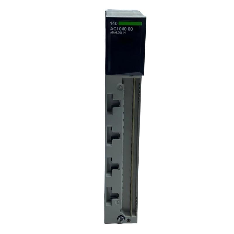
The Schneider 140ACI04000C Analog Input Module is used to acquire analog process signals and transfer measured values into a Modicon Quantum control system. Proper installation of the Schneider 140ACI04000C requires correct module positioning, secure wiring, appropriate signal grounding, configuration of the control system, and systematic commissioning. Because terminal assignments and supported signal characteristics can depend on the installed system and documentation revision, technicians should always verify the exact wiring information before energizing the module.
Schneider 140ACI04000C Analog Input Module Overview
The 140ACI04000C is an analog input module designed for industrial automation applications where field instruments provide continuously varying process signals. Unlike a discrete input module, which primarily detects ON/OFF conditions, an analog input module converts a continuously changing electrical signal into usable process data for the PLC.
In a typical application, the signal path can be represented as:
Field Sensor / Transmitter
        ↓
Field Wiring
        ↓
140ACI04000C Analog Input Module
        ↓
Quantum I/O System
        ↓
PLC Processor
        ↓
Control Logic / HMI / SCADA
The module therefore provides an important interface between field instrumentation and the control program. Stable installation is essential because analog signals can be affected by electrical noise, grounding problems, incorrect wiring, and poor cable routing.
Installation Preparation for Schneider 140ACI04000C
Before installing the 140ACI04000C, confirm that the control cabinet, rack, power system, field devices, and PLC configuration are suitable for the intended application.
- Confirm the exact module model and hardware revision.
- Inspect the module for cracks, damaged connectors, corrosion, or contamination.
- Verify that the Quantum rack and power arrangement are ready for the module.
- Identify every field signal connected to the analog input system.
- Prepare properly rated instrumentation cable.
- Separate analog signal wiring from high-current and high-frequency power wiring.
- Check cabinet grounding and shielding arrangements.
- Confirm the intended PLC configuration before commissioning.
- Make sure the field instruments are compatible with the configured input channels.
Mounting the 140ACI04000C in the Control System
Install the Schneider 140ACI04000C in the appropriate Quantum I/O rack position according to the system architecture. Before insertion or removal, follow the site’s approved electrical isolation procedure and the applicable rack maintenance requirements.
The module should be installed firmly so that its connectors are completely engaged. Loose mechanical connections can create intermittent communication or signal problems that may initially appear to be software faults.
Panel Installation Considerations
- Maintain sufficient cabinet space for wiring and service access.
- Avoid installing the analog module directly beside sources of excessive electromagnetic interference.
- Keep analog signal cables away from motor cables and variable-frequency drive output cables.
- Provide appropriate ventilation for the overall rack assembly.
- Ensure the module remains accessible for inspection and replacement.
Schneider 140ACI04000C Wiring and Signal Integration
Wiring is one of the most important stages when installing an analog input module. The exact terminal arrangement should be checked against the applicable Schneider documentation for the 140ACI04000C and the specific Quantum hardware configuration. Do not assume that terminal positions are identical across different module families.
Before connecting field wiring, identify the signal source, return path, shield arrangement, and expected electrical behavior for each channel.
Analog Signal Wiring Practices
- Use dedicated instrumentation cable where practical.
- Keep signal cables physically separated from power conductors.
- Avoid unnecessary cable loops inside the cabinet.
- Use consistent wire identification throughout the control system.
- Terminate shields according to the plant grounding standard.
- Do not create unintended ground loops.
- Verify polarity before energizing the field circuit.
For long-distance instrumentation connections, cable resistance, electromagnetic interference, and grounding conditions should be considered during engineering rather than after commissioning problems occur.
140ACI04000C PLC Configuration and Setup
After the hardware has been installed and wired, configure the module within the applicable Modicon Quantum control environment. The engineering configuration should correspond to the actual hardware installed in the rack.
- Confirm the rack and module position.
- Enter the correct module identification in the PLC configuration.
- Configure the applicable input characteristics required by the application.
- Assign the required input addresses or variables.
- Download or apply the configuration according to the site’s commissioning procedure.
- Check the PLC diagnostic information.
- Confirm that the module is recognized correctly.
Do not modify scaling or signal interpretation simply to compensate for an incorrect physical connection. Hardware wiring, module configuration, PLC scaling, and the field transmitter must all correspond.
Schneider 140ACI04000C Commissioning Procedure
Commissioning should proceed from the physical layer toward the control application. This makes it easier to isolate wiring, hardware, configuration, and software problems.
Visual Inspection
      ↓
Rack / Module Verification
      ↓
Field Wiring Verification
      ↓
Power-Up
      ↓
Module Diagnostic Check
      ↓
PLC Configuration Check
      ↓
Field Signal Verification
      ↓
Input Value Verification
      ↓
HMI / SCADA Verification
      ↓
Final Functional Test
Step 1: Perform a Visual Inspection
Inspect the module, rack, wiring, connectors, and cabinet before applying power. Look for loose wires, damaged insulation, incorrectly seated connectors, and signs of overheating.
Step 2: Verify the Module Status
After power is applied, check the available module and rack diagnostic indications. An unexpected diagnostic condition should be investigated before continuing with process testing.
Step 3: Verify Field Signals
Check each connected field device using an appropriate test instrument. The objective is to determine whether the expected signal is actually reaching the module input.
Step 4: Verify PLC Values
Compare the physical field condition with the value reported by the PLC. A stable field signal should normally produce a correspondingly stable input value after correct configuration and scaling.
Step 5: Test the Complete Control Loop
Where plant procedures permit, vary the process input through an appropriate operating range and confirm that the PLC, HMI, alarm logic, and control functions respond correctly.
Schneider 140ACI04000C Installation Validation Checklist
- Correct 140ACI04000C model installed.
- Module securely seated in the rack.
- Field wiring checked against the applicable terminal documentation.
- Signal polarity verified.
- Shielding and grounding checked.
- Analog cables separated from major interference sources.
- PLC hardware configuration completed.
- Module diagnostics normal.
- Input values correspond to field conditions.
- HMI and SCADA values verified where applicable.
- Alarms and control logic tested.
Representative 140ACI04000C Commissioning Case
Consider a representative process installation in which an analog transmitter is connected to a 140ACI04000C input. During initial commissioning, the PLC value remains near its minimum even though the process instrument indicates a normal operating condition.
The technician first checks the transmitter and confirms that it is operating normally. The next inspection reveals that the signal return conductor is connected to an incorrect terminal. After correcting the wiring according to the applicable module documentation, the PLC value changes to the expected range.
This example illustrates an important commissioning principle: when an analog value is incorrect, check the complete signal path before changing PLC scaling or application logic.
140ACI04000C Installation FAQs
What is the Schneider 140ACI04000C used for?
The 140ACI04000C is an analog input module used to acquire process instrumentation signals and make the resulting input data available to a Modicon Quantum control system.
Can the 140ACI04000C be installed without checking the terminal diagram?
No. The exact terminal arrangement should always be verified against the applicable documentation before field wiring is connected.
Why should analog cables be separated from power cables?
Analog signals are susceptible to electrical interference. Physical separation helps reduce the possibility of noise being coupled into the measurement circuit.
What should be checked if the module is installed but no useful signal appears?
Check module seating, field wiring, signal source operation, grounding, configuration, PLC addressing, and signal scaling in a structured sequence.
Technical Summary
Installing the Schneider 140ACI04000C Analog Input Module correctly requires more than inserting the module into a Quantum rack. Reliable operation depends on correct hardware installation, disciplined analog wiring, appropriate grounding and shielding, accurate PLC configuration, and controlled commissioning. By verifying the complete signal path from the field instrument to the PLC application, technicians can reduce commissioning errors and establish a stable analog measurement system.