

ProductPRODUCT
Featured products
Contact Us
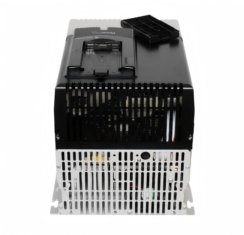
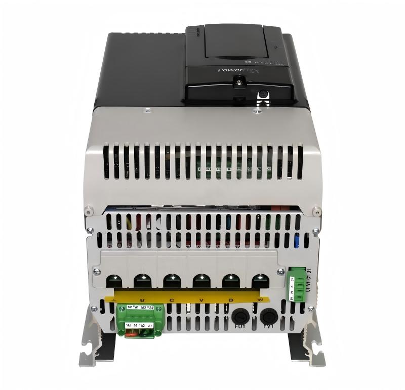
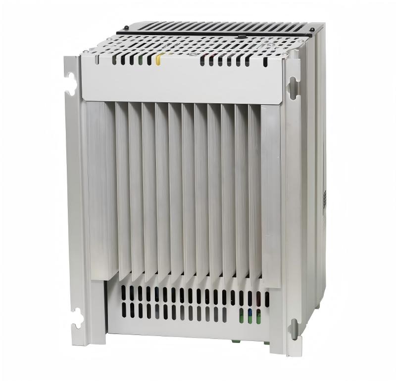
- Allen Bradley
- 20J1F3F920LNDNNNNN
- PowerFlex AC Drive
- USA
- 2477 × 1200 × 800 mm
- 1000 kg
- Xiamen, China
- New & In Stock
- T/T, PayPal, Western Union
- 1 Year
- 1-3 Working Days
- DHL, UPS, TNT, FedEx and EMS.
- 24-Hour Service
- COO
- 3
Our advantage

Global Logistics
We have a 10-year logistics and express cooperation agreement, so our products can be shipped to any place in the world.

Brand new and original
Our products are imported in bulk from the place of origin. Because of the cooperative relationship, our products are all original and 100% new.

24-hour service
We provide 7*24 hours service to our customers. We will be there whenever you need us.

Price advantage
All our products are priced very favorably because we have our own warehouse and supply.
| Company Information | |||
| [email protected] | |||
| Mobile | +8615980777398 | ||
| +8615980777398 | |||
| 15980777398 |
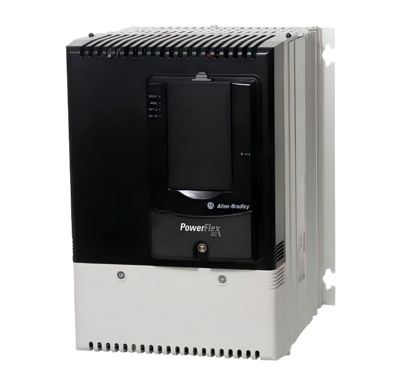
Allen-Bradley 20J1F3F920LNDNNNNN — Detailed Product Specifications, Applications, Advantages and Related Models
1. Product Overview
The 20J1F3F920LNDNNNNN is a high-power regenerative bus supply designed for demanding industrial drive systems where a stable common DC bus, regenerative energy handling, and reduced harmonic distortion are important.
It belongs to the PowerFlex 755T Bus Supplies family and is associated with the PowerFlex 755TM platform. The unit is an air-cooled, regenerative and low-harmonic bus supply intended for large industrial installations.
The product is designed around an Active Front End (AFE) architecture. Instead of operating like a conventional diode or SCR front end that simply converts incoming AC power into DC power, an AFE can actively control the relationship between the AC supply and the DC bus.
This makes the 20J1F3F920LNDNNNNN particularly suitable for applications where electrical regeneration is required, where several drives share a common DC bus, or where reducing the harmonic impact of large variable-frequency drive systems is important.
The unit is rated for 690 VAC, three-phase input power and is intended for high-capacity industrial drive systems.
Its high current capability places it in the large-frame category of industrial power conversion equipment. It is therefore normally associated with large machinery, high-power production equipment, process lines, heavy material handling systems, and other applications where conventional individual drive arrangements may become inefficient or difficult to manage.
The basic product configuration is Type 1/IP21, floor-mounted and air-cooled.
2. Brand and Product Series
| Item | Specification |
|---|---|
| Brand | Allen-Bradley |
| Product Family | PowerFlex 750 Bus Supplies |
| Product Series | PowerFlex 755T Bus Supplies |
| Platform | PowerFlex 755TM |
| Model | 20J1F3F920LNDNNNNN |
| Product Type | Regenerative Low-Harmonic Bus Supply |
| Cooling Method | Air Cooled |
| Installation | Floor Mount |
| Enclosure | Type 1 / IP21 |
| Input Architecture | Active Front End, Regenerative |
| Input Voltage | 690 VAC |
| Input Phase | Three Phase |
| Frame | Large Frame, Frame 9-class configuration |
| Dynamic Braking | None |
| Application | Common DC Bus / Regenerative Drive Systems |
The PowerFlex 755T family is intended for applications requiring more sophisticated power management than a conventional standalone variable-frequency drive.
The 20J1F3F920LNDNNNNN is specifically suited to installations in which a common DC bus is used to distribute DC power to multiple drive sections.
This architecture can simplify the overall power system when a machine contains multiple coordinated motor drives.
3. Main Technical Parameters
| Parameter | 20J1F3F920LNDNNNNN |
|---|---|
| Model | 20J1F3F920LNDNNNNN |
| Brand | Allen-Bradley |
| Series | PowerFlex 755T |
| Product Family | PowerFlex 750 Bus Supplies |
| Product Type | Regenerative & Low-Harmonic Bus Supply |
| Cooling | Air Cooled |
| Input Type | AFE Regenerative |
| Input Voltage | 690 VAC |
| Input Frequency | 50/60 Hz class industrial supply |
| Phase | 3 Phase |
| Enclosure | Type 1 / IP21 |
| Mounting | Floor Mount |
| Frame | Frame 9-class |
| Dynamic Braking | None |
| Long-Duty Rating | Approx. 1102 kW / 1102 A |
| Normal-Duty Rating | Approx. 944 kW / 944 A |
| Heavy-Duty Rating | Approx. 842 kW / 842 A |
| Regeneration | Yes |
| Harmonic Reduction | Low-Harmonic AFE Architecture |
| DC Bus Architecture | Common DC Bus |
| Cooling System | Forced Air Cooling |
| Typical Application | Large Industrial Drive Systems |
| Dimensions | Approx. 1,200–1,600 W × 800–1,100 D × 2,000–2,400 H mm* |
| Weight | Approx. 800–1,200 kg* |
* Dimensions and weight can vary according to the exact cabinet configuration, options, power connections, enclosure arrangement, installed accessories and regional configuration. For engineering installation, the actual equipment nameplate and mechanical drawing should be treated as the final dimensional reference.
The model is a very high-power unit. The approximately 1102 kW long-duty rating places it well above the power level normally associated with compact industrial drives.
The combination of high voltage and high current makes this type of equipment appropriate for large-scale industrial systems rather than small machine applications.
4. Understanding the Model 20J1F3F920LNDNNNNN
The catalog number contains configuration information describing the electrical and mechanical characteristics of the product.
The important part for system selection is that the model belongs to the 20J1 PowerFlex 750 Bus Supply family and uses the F-series 690 VAC configuration.
The F920 portion identifies a high-current configuration within this family.
The model is therefore not simply a conventional motor inverter. It is a large regenerative power conversion unit intended to create and manage a common DC bus for compatible PowerFlex drive equipment.
This distinction is important when comparing the product with standard PowerFlex 753 or PowerFlex 755 standalone drives.
A conventional drive normally receives AC power and directly supplies one motor.
The 20J1F3F920LNDNNNNN, by contrast, can function as the front-end power conversion section for a larger multi-drive system.
5. Product Introduction
The 20J1F3F920LNDNNNNN is designed for large industrial installations that require controlled AC-to-DC conversion and the ability to return regenerated energy to the incoming electrical supply.
When an industrial motor is accelerating, electrical energy flows from the AC supply toward the motor.
When the motor decelerates or an external mechanical load drives the motor faster than its commanded speed, the motor can operate as a generator.
This regenerated energy is transferred back toward the DC bus.
In a conventional drive system, regenerated energy may need to be dissipated through braking resistors.
That approach converts excess electrical energy into heat.
The regenerative architecture used by the 20J1F3F920LNDNNN instead provides a controlled path for returning regenerated energy back to the AC supply.
This is particularly useful for systems containing repeated acceleration and deceleration cycles.
It can also be valuable in applications where large mechanical loads continuously exchange energy between motor and drive system.
6. Active Front End Technology
One of the most important characteristics of the 20J1F3F920LNDNNNNN is its Active Front End architecture.
An AFE uses actively controlled power semiconductor devices to manage the conversion between AC power and the DC bus.
The front end can control the current waveform much more precisely than a basic passive rectifier.
This provides several important system-level benefits.
The first benefit is improved control of input current.
The second benefit is the ability to support regenerative operation.
The third benefit is reduced harmonic current compared with conventional six-pulse rectification.
The fourth benefit is improved control of power flow between the AC system and the DC bus.
For a large industrial installation, these characteristics can become particularly important because the electrical consequences of a large conventional rectifier increase as system power increases.
7. Regenerative Operation
Regeneration is one of the main reasons to select this type of bus supply.
During braking, lowering, deceleration, or overhauling-load conditions, the connected motor can send energy back into the DC bus.
The 20J1F3F920LNDNNN can transfer this energy from the DC bus back into the AC power system.
This avoids relying solely on braking resistors for energy dissipation.
The resulting system can be particularly effective for equipment with frequent braking cycles.
Typical examples include cranes, hoists, elevators, test stands, high-inertia machinery, conveyors with overhauling loads, centrifuges, and large process machines.
In a large production line, several drives can also exchange energy through the common DC bus.
For example, one motor may be braking while another motor is accelerating.
Instead of immediately dissipating the braking energy as heat, the common DC bus can allow the energy to be reused by another drive.
This can improve overall system energy utilization.
8. Low-Harmonic Operation
Large AC drives can introduce harmonic currents into an electrical distribution system.
As drive power increases, harmonic management becomes increasingly important.
The 20J1F3F920LNDNNNNN uses an active front-end architecture designed for low-harmonic operation.
The front end actively shapes the input current waveform.
This can reduce the harmonic current contribution associated with conventional rectifier front ends.
Low-harmonic operation can be valuable in facilities where multiple large drives operate simultaneously.
It can also simplify the design of electrical distribution systems where power-quality requirements are important.
Typical considerations include transformers, switchgear, generators, capacitor systems, protection equipment and other connected loads.
The exact harmonic performance of a complete installation still depends on the complete system design, operating conditions and applicable electrical standards.
9. High-Power Capability
The 20J1F3F920LNDNNN is intended for extremely large drive applications.
Its approximate ratings include:
| Duty Category | Approx. Power | Approx. Current |
|---|---|---|
| Long Duty | 1102 kW | 1102 A |
| Normal Duty | 944 kW | 944 A |
| Heavy Duty | 842 kW | 842 A |
The different duty categories allow the same general product class to be applied to different load requirements.
Long-duty operation is typically associated with applications where the required continuous output capability is the primary selection factor.
Normal-duty operation is suitable for applications with somewhat different load characteristics.
Heavy-duty operation is intended for applications involving greater overload requirements.
The actual drive-system selection should always consider motor current, acceleration requirements, overload duration, duty cycle, ambient conditions and the complete application profile.
10. Common DC Bus Architecture
The common DC bus concept is another major feature of the product family.
Instead of installing a complete AC input section for every individual motor drive, a common bus system can provide DC power to multiple drive inverter sections.
This approach can be advantageous for machines containing multiple motors.
For example, a production line could contain:
- Main conveyor drives
- Auxiliary conveyor drives
- Roll drives
- Winder drives
- Unwinder drives
- Pump drives
- Fan drives
- Hoist drives
- Process drives
A common DC bus can connect these drive sections into a coordinated electrical system.
This can reduce duplicated front-end equipment and create opportunities for regenerative energy sharing.
11. Product Applications
The 20J1F3F920LNDNNN is most appropriate for large and complex industrial systems.
Steel Processing Equipment
Steel processing lines frequently contain multiple motors operating at high power levels.
Rolling mills, finishing lines, processing lines and material-handling systems can contain numerous interconnected drives.
A common DC bus with regenerative capability can provide an effective architecture for these systems.
Metal Processing Machinery
Large metal-processing equipment often experiences significant acceleration and deceleration.
Regenerative capability can become valuable where high-inertia mechanical systems are repeatedly slowed down.
The 20J1F3F920LNDNNNNN can be used as part of a coordinated drive system where multiple motor sections operate from a shared DC bus.
Cranes and Hoists
Cranes and hoists are classic regenerative applications.
When a load is lowered, mechanical energy can drive the motor.
The motor then behaves as a generator and sends energy back to the electrical system.
A regenerative front end can handle this energy without depending entirely on braking resistors.
Elevators and Vertical Transportation
Large elevators can have significant regenerative energy during downward travel or deceleration.
In large installations, regeneration can be integrated into the facility electrical system.
The common DC bus architecture can also be useful where multiple motor sections need to operate in coordination.
Material Handling
Large conveyors and material-handling systems can require multiple motors.
A shared DC bus can provide a coordinated power architecture.
Regeneration can also be useful when large rotating masses need to be repeatedly accelerated and decelerated.
Mining Equipment
Mining equipment often operates under severe mechanical loads.
Large conveyors, crushers, hoists and processing equipment can require very high motor power.
The 20J1F3F920LNDNNN is well suited to the electrical power range encountered in some large mining applications.
Cement and Aggregate Processing
Large crushers, mills, fans and conveyors can require substantial drive power.
For multi-drive plants, a common DC bus can help create a centralized drive architecture.
Test Stands
Industrial test stands can deliberately accelerate and decelerate motors or mechanical loads.
Regeneration can therefore become a major consideration.
An AFE system can return energy to the AC supply rather than dissipating it through conventional braking equipment.
Large Process Machinery
Chemical, petrochemical, paper, pulp, food processing and other continuous-process industries can contain large numbers of coordinated motors.
Where power ratings and regeneration requirements are high, a PowerFlex 755T bus supply architecture can provide an appropriate foundation.
12. Main Product Advantages
12.1 Regenerative Energy Recovery
The most obvious advantage is regenerative operation.
Instead of converting braking energy directly into heat through braking resistors, the system can return energy to the AC supply.
This can reduce wasted energy in applications with frequent regeneration.
12.2 Low-Harmonic Input
The AFE design allows more precise control of input current.
This can help reduce harmonic distortion compared with conventional passive rectification.
This characteristic becomes more valuable as installed drive power increases.
12.3 High Power Density at System Level
A common bus arrangement can reduce the need for duplicated AC front ends.
For multi-drive machines, this can simplify the overall electrical architecture.
The benefit is especially relevant when many inverter sections are installed together.
12.4 Energy Sharing Between Drives
A common DC bus allows energy to move between connected drive sections.
If one motor is regenerating while another is motoring, the regenerated energy can potentially be used by the other drive.
This provides a more efficient energy-management architecture than treating every drive as an isolated system.
12.5 Suitable for Large Industrial Systems
The 20J1F3F920LNDNNNNN is designed for applications where small and medium-power drives are no longer sufficient.
Its high-current capability makes it suitable for large industrial machines and production systems.
12.6 Reduced Dependence on Dynamic Braking Resistors
Because the product is regenerative, dynamic braking resistors are not the primary mechanism for handling regenerated energy.
This can reduce the amount of heat generated by braking systems.
It may also simplify thermal management in applications with heavy regenerative duty.
12.7 Flexible System Architecture
The common bus concept allows engineers to configure multiple drive inverter sections around a centralized power-conversion system.
This can be useful when the machine contains multiple coordinated axes.
13. Mechanical and Installation Characteristics
The product is an industrial floor-mounted unit rather than a compact cabinet-mounted drive.
The Type 1/IP21 enclosure configuration is intended for controlled indoor industrial environments.
The air-cooled design requires appropriate ventilation.
Large power electronic systems generate substantial heat during operation.
Adequate cabinet clearance, airflow, ambient temperature control and maintenance access are therefore important.
The installation area should provide enough space for:
- Incoming power connections
- DC bus connections
- Cooling airflow
- Service access
- Inspection
- Cable routing
- Grounding
- Protective devices
- Maintenance activities
Because this is a large-frame power conversion unit, mechanical planning should be completed before installation.
14. Approximate Dimensions and Weight
The exact physical dimensions can vary according to configuration.
For planning purposes, a unit of this power class can be treated as a large floor-mounted industrial cabinet.
| Mechanical Parameter | Approximate Value |
|---|---|
| Width | Approx. 1,200–1,600 mm |
| Depth | Approx. 800–1,100 mm |
| Height | Approx. 2,000–2,400 mm |
| Weight | Approx. 800–1,200 kg |
| Mounting | Floor Mount |
| Cooling | Air Cooled |
| Enclosure | Type 1 / IP21 |
These values should be considered engineering estimates rather than guaranteed factory dimensions.
The final shipping weight and cabinet dimensions depend on the exact configuration, options, disconnect arrangements, auxiliary equipment, packaging and enclosure construction.
For installation drawings, lifting plans and foundation design, the exact configuration drawing should be used.
15. Electrical System Advantages
A large regenerative bus supply can influence the electrical design of an entire production line.
The 20J1F3F920LNDNNN can provide a centralized power-conversion point for multiple drives.
This can make the power architecture easier to organize.
The AFE can also provide controlled input current characteristics.
For facilities with large installed drive capacity, this can be important for maintaining acceptable electrical power quality.
The regenerative function provides another system-level advantage because braking energy does not have to be treated exclusively as waste heat.
16. Maintenance Considerations
Because the product is a high-power air-cooled system, preventive maintenance should pay particular attention to cooling and electrical connections.
Cooling airflow should remain unobstructed.
Fans and ventilation paths should be inspected according to the maintenance schedule.
Electrical connections should be inspected for signs of overheating, looseness or abnormal discoloration.
The DC bus requires appropriate safety procedures because dangerous voltage can remain present after incoming AC power is removed.
Maintenance personnel should follow the applicable lockout/tagout and electrical safety procedures before opening or servicing the equipment.
The actual maintenance interval should be determined from the equipment documentation, operating environment and application duty.
17. Typical System Configuration
A typical large PowerFlex 755T system using this type of bus supply can be conceptually arranged as follows:
AC Power Supply
↓
20J1F3F920LNDNNNNN Regenerative AFE Bus Supply
↓
Common DC Bus
↓
Multiple PowerFlex Drive Inverter Sections
↓
Industrial Motors / Mechanical Loads
This arrangement separates the AC front-end power conversion function from the individual motor inverter sections.
The architecture is particularly useful when many motors need to operate as part of one coordinated machine.
18. Five Related Models from the Same Series
The following models are closely related PowerFlex 755T bus-supply configurations and can be considered when selecting a different power level or electrical configuration.
| Model | Series | Cooling | Voltage Class | LD Rating | ND Rating | HD Rating | Enclosure |
|---|---|---|---|---|---|---|---|
| 20J1F3F735LNDNNNNN | PowerFlex 755T | Air Cooled | 690 VAC | 842 kW / 842 A | 754 kW / 754 A | 667 kW / 667 A | Type 1/IP21 |
| 20J1F3F505LNDNNNNN | PowerFlex 755T | Air Cooled | 690 VAC | 580 kW / 580 A | 518 kW / 518 A | 426 kW / 426 A | Type 1/IP21 |
| 20J1F3C770LNDNNNNN | PowerFlex 755T | Air Cooled | 690 VAC class | 518 kW / 893 A | 479 kW / 826 A | 405 kW / 698 A | Type 1/IP21 |
| 20J1F3D740LNDNNNNN | PowerFlex 755T | Air Cooled | 690 VAC class | 573 kW / 823 A | 529 kW / 761 A | 442 kW / 635 A | Type 1/IP21 |
| 20J1F3D960LNDNNNNN-C1 | PowerFlex 755T | Air Cooled | 690 VAC class | 748 kW / 1075 A | 687 kW / 987 A | 573 kW / 823 A | Type 1/IP21 |
These models cover different combinations of power, current and configuration.
The most direct comparison for the 20J1F3F920LNDNNNNN is the 20J1F3F735LNDNNNNN because it remains within the same 690 VAC air-cooled regenerative bus-supply concept while offering a lower capacity.
The 20J1F3F505LNDNNNNN is another useful comparison for applications where the required power is substantially lower.
The 20J1F3D740LNDNNNNN and 20J1F3C770LNDNNNNN are useful alternatives when the application requires different current and power combinations.
19. Related Model Comparison
| Model | Approx. LD Power | Approx. ND Power | Approx. HD Power | General Position |
|---|---|---|---|---|
| 20J1F3F505LNDNNNNN | 580 kW | 518 kW | 426 kW | Medium-high power |
| 20J1F3D740LNDNNNNN | 573 kW | 529 kW | 442 kW | Medium-high power |
| 20J1F3C770LNDNNNNN | 518 kW | 479 kW | 405 kW | Medium-high power |
| 20J1F3F735LNDNNNNN | 842 kW | 754 kW | 667 kW | High power |
| 20J1F3F920LNDNNNNN | 1102 kW | 944 kW | 842 kW | Very high power |
The 20J1F3F920LNDNNNNN sits toward the high-capacity end of these air-cooled PowerFlex 755T bus-supply configurations.
For applications below approximately 600 kW, smaller related models may be more appropriate.
For applications approaching or exceeding the 1 MW range, the 20J1F3F920LNDNNNNN provides a substantially larger power envelope.
20. Five Popular Models from the Same Brand
The following models represent commonly encountered products within the broader Allen-Bradley PowerFlex drive portfolio.
| Model | Product Family | Typical Voltage Class | Approx. Power Range | Main Application |
|---|---|---|---|---|
| 25B-D017N114 | PowerFlex 525 | 380–480 VAC | Approx. 7.5 kW class | Compact machine drives |
| 20F11NC022JA0NNNNN | PowerFlex 753 | 380–480 VAC class | Medium-power range | General industrial drives |
| 20F11NC034JA0NNNNN | PowerFlex 753 | 380–480 VAC class | Medium/high-power range | Industrial machinery |
| 20G1ANB140JA0NNNNN | PowerFlex 755 | 380–480 VAC class | High-power range | Advanced industrial drives |
| 20G1ANC350JA0NNNNN | PowerFlex 755 | 380–480 VAC class | High-power range | Large industrial machinery |
These products cover a much wider range of applications than the 20J1F3F920LNDNNNNN.
The PowerFlex 525 is oriented toward compact machine applications.
The PowerFlex 753 and PowerFlex 755 families are intended for larger and more sophisticated industrial drive applications.
The 20J1F3F920LNDNNNNN is different because it is a dedicated regenerative bus-supply product rather than simply a conventional standalone motor drive.
21. Broader Product Family Comparison
| Product | Primary Function | Typical Application Scale | Regeneration Capability | Common DC Bus |
|---|---|---|---|---|
| PowerFlex 525 / 25B series | Compact VFD | Small to medium machines | Application dependent | No primary focus |
| PowerFlex 753 / 20F series | Industrial VFD | Medium to large machinery | Configuration dependent | Available in system architectures |
| PowerFlex 755 / 20G series | Advanced industrial VFD | Large machinery | Configuration dependent | Supported |
| 20J1F3F920LNDNNNNN | Regenerative AFE bus supply | Very large multi-drive systems | Yes | Yes |
| PowerFlex 755T Bus Supply Family | Regenerative / low-harmonic power conversion | Large multi-drive systems | Yes | Yes |
22. Why a Common DC Bus Can Be Useful
A common DC bus becomes especially useful when a machine has several motors that operate at different times.
Imagine a production machine with four major motor sections.
Motor A is accelerating.
Motor B is running at constant speed.
Motor C is braking.
Motor D is accelerating.
Motor C may be returning energy to the DC bus while Motors A and D are consuming energy.
This creates an opportunity for energy to move directly within the machine’s electrical system.
The common DC bus therefore becomes more than just a power distribution point.
It can function as an energy-sharing network between the different drive sections.
23. Regeneration Compared with Braking Resistors
Traditional braking systems often use resistors to absorb excess DC bus energy.
The electrical energy is converted into heat.
This method is relatively straightforward, but the heat must then be removed from the cabinet or surrounding environment.
In applications with frequent regeneration, this can create significant thermal loads.
A regenerative AFE changes the approach.
Instead of primarily dissipating the energy, the system can transfer it back toward the AC supply.
This can reduce braking-related heat generation and improve energy utilization.
The benefit becomes more noticeable in applications with frequent high-energy braking events.
24. Application Example — Large Conveyor System
Consider a large conveyor installation with multiple motor sections.
The conveyor may have several drive motors distributed along the production line.
During startup, several motors require substantial electrical power.
During normal operation, the motors operate at relatively stable load levels.
During a controlled stop, the mechanical inertia of the conveyor continues to drive the motors.
Those motors can enter regeneration.
With a regenerative common DC bus architecture, the recovered energy can be managed through the DC bus and returned to the AC system.
This can provide a more coordinated power-management solution than treating every motor as an independent drive.
25. Application Example — Crane and Hoist System
A large crane can alternate between lifting and lowering heavy loads.
During lifting, the motor consumes large amounts of power.
During lowering, gravity drives the mechanical system.
The motor can then become a generator.
This creates a substantial regeneration event.
The 20J1F3F920LNDNNNNN can be used as part of a regenerative drive system capable of handling this type of bidirectional energy flow.
This is one of the clearest examples of why regenerative front-end technology can be valuable.
26. Application Example — Metal Processing Line
A metal-processing line may contain many motors.
One section may accelerate a strip of material.
Another section may control tension.
A third section may decelerate.
A fourth section may maintain constant speed.
The motors can therefore exchange energy continuously.
A common DC bus provides a convenient electrical architecture for coordinating these loads.
The regenerative capability allows energy generated by braking sections to be managed efficiently.
27. Application Example — Test and Dynamometer Systems
Test equipment can require repeated acceleration and deceleration.
A motor under test may be accelerated to a target speed and then rapidly decelerated.
The kinetic energy stored in the rotating equipment is returned through the motor into the DC bus.
In a conventional system, this energy may need to be dissipated.
A regenerative system can send it back into the AC supply.
This can be particularly valuable when the test cycle is repeated hundreds or thousands of times.
28. Product Advantages for System Designers
From an engineering perspective, the 20J1F3F920LNDNNNNN provides several useful characteristics.
High-Power Capacity
The unit is intended for large drive systems and can support approximately 1 MW-class operation.
Regenerative Operation
The system can handle energy flowing back from connected drives.
Low-Harmonic Input
The AFE architecture provides controlled input-current characteristics.
Common DC Bus
Multiple drive sections can share a centralized DC power source.
Energy Sharing
Regenerative energy from one drive can potentially support another connected drive.
Reduced Braking Heat
Regeneration can reduce the amount of energy that must be converted into heat through braking resistors.
Industrial Construction
The floor-mounted cabinet configuration is suitable for industrial power rooms and large machinery installations.
System-Level Flexibility
The bus-supply architecture allows different inverter sections to be combined into a coordinated drive system.
29. Important Installation Factors
When designing an installation around this model, several factors should be considered.
Electrical Supply
The incoming electrical system must be suitable for the 690 VAC three-phase input configuration.
The upstream transformer, switchgear, protective devices and cabling must be sized for the complete system.
Short-Circuit Rating
The available fault current at the installation point must be considered.
Protection and coordination should be designed according to the applicable electrical standards and the complete system configuration.
Cooling
Air-cooled power electronics require adequate airflow.
The installation environment should not restrict the cooling system.
High ambient temperature can affect the usable output capability of power electronic equipment.
Cable Routing
High-power AC and DC connections require careful routing.
Cable size, insulation, separation, grounding and termination methods must be designed appropriately.
Grounding
Correct protective grounding is essential for a high-power industrial drive installation.
Grounding design should consider both electrical safety and system electromagnetic compatibility.
Maintenance Access
The cabinet must have sufficient front and service clearance.
Large power-conversion systems should not be installed where routine inspection or component replacement is difficult.
30. Product Selection Considerations
The 20J1F3F920LNDNNNNN should not be selected solely from the motor horsepower.
The following factors should also be considered:
| Selection Factor | Why It Matters |
|---|---|
| Motor Current | Determines required drive capacity |
| Motor Voltage | Must match system voltage class |
| Duty Cycle | Determines thermal loading |
| Overload Requirement | Determines appropriate duty rating |
| Regeneration | Determines need for AFE |
| Number of Drives | Influences common DC bus architecture |
| Harmonic Requirements | Influences front-end selection |
| Ambient Temperature | Influences thermal performance |
| Installation Altitude | Can affect cooling and ratings |
| Enclosure Requirement | Determines environmental protection |
| Cable Length | Influences system design |
| Braking Requirements | Determines regeneration strategy |
| Power Quality | Influences front-end architecture |
This is especially important for high-power equipment because a small difference in application conditions can have a significant impact on system sizing.
31. Dimensions and Weight — Engineering Planning Table
| Mechanical Item | Approximate Specification |
|---|---|
| Product Type | Large floor-mounted regenerative bus supply |
| Mounting | Floor standing |
| Approx. Width | 1,200–1,600 mm |
| Approx. Depth | 800–1,100 mm |
| Approx. Height | 2,000–2,400 mm |
| Approx. Weight | 800–1,200 kg |
| Cooling | Air cooled |
| Enclosure | Type 1 / IP21 |
| Service Access | Front/service area required |
| Transportation | Industrial lifting equipment normally required |
Because the 20J1F3F920LNDNNN is a large-frame power system, the final mechanical design should not rely on generic dimensions.
The exact configuration can change cabinet dimensions and weight.
For transportation planning, lifting, foundation loading and final equipment layout, the actual configured unit should be checked.
32. Product Specification Summary
| Category | Specification |
|---|---|
| Model | 20J1F3F920LNDNNNNN |
| Brand | Allen-Bradley |
| Series | PowerFlex 755T |
| Platform | PowerFlex 755TM |
| Family | PowerFlex 750 Bus Supplies |
| Type | Regenerative Low-Harmonic Bus Supply |
| Input Technology | Active Front End |
| Voltage | 690 VAC |
| Phase | 3 Phase |
| Cooling | Air Cooled |
| Enclosure | Type 1 / IP21 |
| Mounting | Floor Mount |
| Dynamic Braking | None |
| LD | 1102 kW / 1102 A |
| ND | 944 kW / 944 A |
| HD | 842 kW / 842 A |
| DC Bus | Common DC Bus |
| Regenerative Function | Yes |
| Harmonic Reduction | Yes |
| Approx. Dimensions | 1,200–1,600 × 800–1,100 × 2,000–2,400 mm |
| Approx. Weight | 800–1,200 kg |
| Main Market | Heavy Industrial Automation |
| Typical Systems | Multi-drive, regenerative, high-power systems |
33. Recommended Related Models at a Glance
| Model | Approx. LD | Approx. ND | Approx. HD | Main Reason to Consider |
|---|---|---|---|---|
| 20J1F3F505LNDNNNNN | 580 kW | 518 kW | 426 kW | Lower power alternative |
| 20J1F3D740LNDNNNNN | 573 kW | 529 kW | 442 kW | Similar mid-high power range |
| 20J1F3C770LNDNNNNN | 518 kW | 479 kW | 405 kW | Lower current/power configuration |
| 20J1F3F735LNDNNNNN | 842 kW | 754 kW | 667 kW | High-power alternative |
| 20J1F3D960LNDNNNNN-C1 | 748 kW | 687 kW | 573 kW | Different high-current configuration |
34. Recommended Same-Brand Models at a Glance
| Model | Family | General Power Class | Typical Application |
|---|---|---|---|
| 25B-D017N114 | PowerFlex 525 | Low/medium | Compact machinery |
| 20F11NC022JA0NNNNN | PowerFlex 753 | Medium | General industrial automation |
| 20F11NC034JA0NNNNN | PowerFlex 753 | Medium/high | Industrial machinery |
| 20G1ANB140JA0NNNNN | PowerFlex 755 | High | Advanced industrial systems |
| 20G1ANC350JA0NNNNN | PowerFlex 755 | High | Large industrial machines |
35. Overall Product Position
The 20J1F3F920LNDNNNNN occupies a very different position from a compact variable-frequency drive.
It is designed as part of a large-scale power architecture.
Its combination of 690 VAC operation, high current capacity, Active Front End technology, regeneration, low-harmonic operation and common DC bus capability makes it appropriate for sophisticated industrial drive systems.
The product is particularly relevant when a machine contains multiple high-power drives and significant regenerative energy.
Instead of treating each motor as an independent electrical load, the common DC bus approach allows the machine to be designed as one coordinated electrical system.
This can provide important advantages in energy management, power quality and overall system architecture.
36. Final Product Description
The Allen-Bradley 20J1F3F920LNDNNNNN is a high-power PowerFlex 755T regenerative and low-harmonic bus supply designed for large industrial automation and multi-drive applications.
It uses an Active Front End to provide controlled AC-to-DC power conversion while supporting regenerative energy flow from the common DC bus back toward the AC electrical system.
With an approximate 1102 kW long-duty rating, 944 kW normal-duty rating and 842 kW heavy-duty rating, it is intended for very large industrial systems where standard compact drives are not sufficient.
Its 690 VAC three-phase input, air-cooled construction, Type 1/IP21 enclosure and floor-mounted configuration make it suitable for large industrial electrical rooms and machine installations.
The strongest application areas include large conveyors, cranes, hoists, metal-processing equipment, mining systems, test stands, production lines, process machinery and other high-power multi-drive systems.
The major technical advantages are regenerative operation, low-harmonic input characteristics, common DC bus architecture, energy sharing between drives and reduced dependence on resistor-based braking.
For applications requiring centralized power conversion for multiple large drives, the 20J1F3F920LNDNNN provides a high-capacity architecture that can be significantly more sophisticated than a conventional standalone variable-frequency drive.
For final engineering selection, cabinet dimensions, shipping weight, electrical protection, cable sizing and installation clearances should be verified against the exact configured unit because these values can change with the selected configuration and installed options.