
NewsNEWCENTER
Featured products
Contact Us
Siemens 6AG1040-1LA00-2AA0 Control Unit Troubleshooting Guide
2026-09-21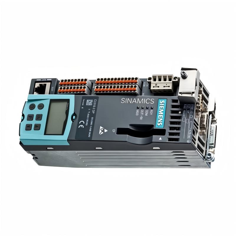
Troubleshooting the Siemens 6AG1040-1LA00-2AA0 Control Unit should begin with a system-level diagnosis of power, grounding, communication, configuration, and connected equipment. If the unit shows an abnormal status, does not communicate, or fails to perform its expected control function, technicians should isolate the fault systematically instead of replacing the control unit immediately.
Siemens 6AG1040-1LA00-2AA0 Fault Diagnosis Overview
A control-unit problem can originate from the unit itself or from another part of the automation system. Power supplies, network connections, configuration data, connected modules, wiring, environmental conditions, and external interference can all produce symptoms that appear to be a control-unit failure.
A practical troubleshooting strategy is therefore to divide the system into several diagnostic layers:
- Power supply and protection.
- Grounding and bonding.
- Physical connections.
- Communication network.
- Configuration and parameterization.
- Control-system logic and connected hardware.
- Control unit hardware.
Siemens 6AG1040-1LA00-2AA0 Common Fault Symptoms
Typical field symptoms may include:
- Control unit does not start.
- Status indication is abnormal.
- Communication with another system component is unavailable.
- Intermittent communication loss occurs.
- Configured devices are not detected correctly.
- Commands do not produce the expected system response.
- Faults appear after cabinet maintenance or wiring changes.
- The system operates normally for a period and then reports communication or control errors.
Common Causes of Siemens 6AG1040-1LA00-2AA0 Faults
| Symptom | Possible Cause | Recommended Check |
|---|---|---|
| No startup | Supply or wiring problem | Verify supply path and protection |
| No communication | Network, connector, or configuration issue | Check physical and configuration layers |
| Intermittent communication | Loose connection or electrical interference | Inspect connectors, routing, grounding, and environment |
| Unexpected control response | Incorrect configuration or external system condition | Compare actual configuration with the approved system design |
| Repeated diagnostic condition | Hardware, configuration, or connected-device fault | Review diagnostics and isolate the affected section |
Siemens 6AG1040-1LA00-2AA0 Troubleshooting Diagnostic Logic
Fault Reported
      |
      v
Check Power
      |
      +---- Fault ----> Correct Supply / Protection
      |
      v
Check Grounding
      |
      +---- Fault ----> Correct Grounding
      |
      v
Check Connectors and Wiring
      |
      +---- Fault ----> Repair Connection
      |
      v
Check Communication
      |
      +---- Fault ----> Check Network / Configuration
      |
      v
Check Diagnostics
      |
      v
Check System Configuration
      |
      v
Test Control Function
      |
      v
Evaluate Hardware
This sequence prevents technicians from confusing an external system problem with an internal control-unit failure.
Siemens 6AG1040-1LA00-2AA0 Testing and Fault Analysis
Testing should be performed with appropriate instruments and according to the site’s electrical safety procedures. For energized systems, only qualified personnel should perform measurements.
Power Verification
Verify the incoming supply at the appropriate measurement point and compare the measured condition with the requirements of the installed system. If the supply is unstable, investigate the upstream protection, power supply, terminals, and wiring before testing the control unit further.
Connection Verification
Inspect connectors and wiring for loose terminals, damaged conductors, contamination, corrosion, or signs of overheating. A connector that is physically present is not necessarily electrically reliable.
Communication Verification
If the unit powers normally but communication fails, check the complete communication path rather than testing only the control unit.
Control Unit
   |
   +-- Connector
   |
   +-- Communication Cable
   |
   +-- Network Device
   |
   +-- Configuration / Address
   |
   +-- Target Control Component
Configuration Verification
Compare the active configuration with the approved machine or process configuration. Incorrect addresses, system assignments, communication parameters, or downloaded configuration data can produce symptoms that resemble hardware failure.
Siemens 6AG1040-1LA00-2AA0 Repair and Replacement Procedure
When testing indicates a hardware problem, first record the existing system condition and configuration. This is especially important when replacing a control unit in an operating automation system.
- Place the equipment in a safe maintenance state.
- Isolate power according to the approved procedure.
- Record wiring and connector positions.
- Identify the complete replacement order number.
- Inspect the replacement unit before installation.
- Transfer or restore the required configuration using the approved method.
- Reconnect wiring carefully and verify every connection.
- Restore power and check diagnostic status.
- Verify communication with associated equipment.
- Perform a controlled functional test.
Do not substitute another Siemens control unit solely because its physical dimensions or connector arrangement appears similar. Electrical, firmware, communication, and configuration compatibility should all be verified before substitution.
Siemens 6AG1040-1LA00-2AA0 Field Troubleshooting Case
Representative example: A control system reports intermittent communication loss from the control unit. The fault occurs only after several hours of operation.
Initial Symptom:
Intermittent communication loss

Initial Assumption:
Possible control-unit failure

Diagnostic Steps:
1. Check supply stability
2. Inspect communication connector
3. Inspect cable routing
4. Check grounding
5. Review communication diagnostics
6. Compare configuration
7. Monitor system operation

Finding:
Communication connection / external installation condition requires correction

Result:
Stable communication after corrective action
The example demonstrates an important maintenance principle: intermittent faults should be investigated under the conditions in which they occur. A control unit should not be replaced solely because communication is unstable.
Siemens 6AG1040-1LA00-2AA0 Troubleshooting FAQ
Why does the Siemens 6AG1040-1LA00-2AA0 not start?
Possible causes include an incorrect or missing supply, upstream protection problems, wiring faults, connector problems, or an internal hardware issue. Begin with the supply path and installation conditions.
What should I check when communication is lost?
Check connectors, communication cables, network equipment, grounding, configuration, addressing, and the status of the connected devices before determining whether the control unit is defective.
Can a configuration error look like a hardware fault?
Yes. Incorrect configuration or communication parameters can prevent expected system operation even when the physical hardware is functioning correctly.
Should the control unit be replaced immediately when a fault appears?
No. A structured diagnosis should first eliminate power, wiring, communication, configuration, and connected-device causes. Replacement is more appropriate after evidence points to a hardware problem.
What information should be recorded before replacing the unit?
Record the complete order number, wiring arrangement, diagnostic indications, configuration information, communication status, and relevant system conditions. This information can simplify restoration and help identify the original failure mechanism.
Siemens 6AG1040-1LA00-2AA0 Technical Summary
The Siemens 6AG1040-1LA00-2AA0 Control Unit should be diagnosed as one element of the complete automation system. A reliable troubleshooting process starts with power and grounding, continues through physical connections and communication, and then examines configuration and hardware. This approach reduces unnecessary replacement and helps maintenance personnel identify the actual source of control-system faults.