

ProductPRODUCT
Featured products








Contact Us
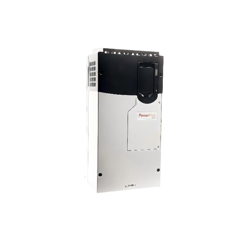
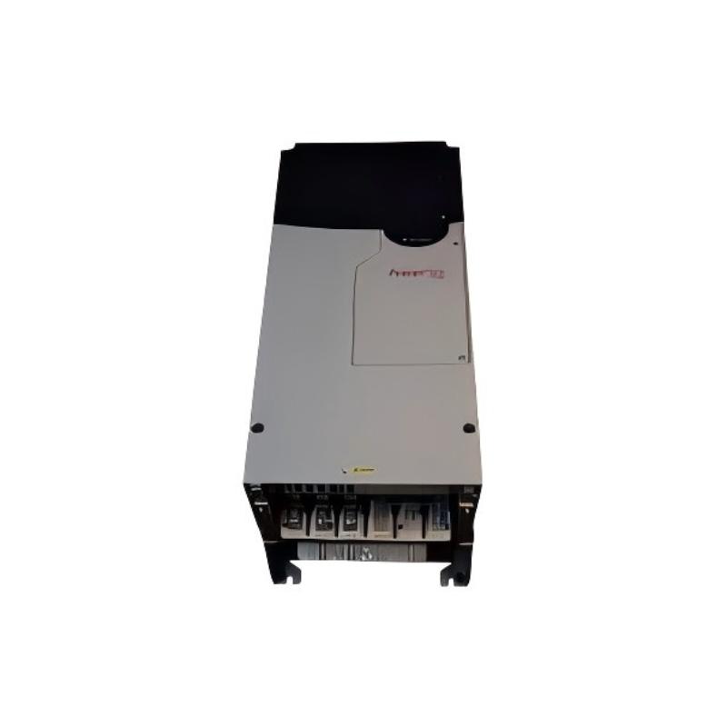
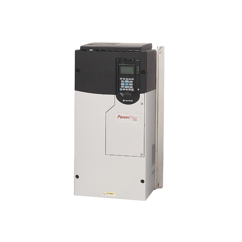
- Allen Bradley
- 20F14NF212JN0NNNNN
- PowerFlex AC Drive
- USA
- 881.5 × 430 × 349.6 mm
- 14.51kg
- Xiamen, China
- New & In Stock
- T/T, PayPal, Western Union
- 1 Year
- 1-3 Working Days
- DHL, UPS, TNT, FedEx and EMS.
- 24-Hour Service
- COO
- 87
Our advantage

Global Logistics
We have a 10-year logistics and express cooperation agreement, so our products can be shipped to any place in the world.

Brand new and original
Our products are imported in bulk from the place of origin. Because of the cooperative relationship, our products are all original and 100% new.

24-hour service
We provide 7*24 hours service to our customers. We will be there whenever you need us.

Price advantage
All our products are priced very favorably because we have our own warehouse and supply.
| Company Information | |||
| [email protected] | |||
| Mobile | +8615980777398 | ||
| +8615980777398 | |||
| 15980777398 |
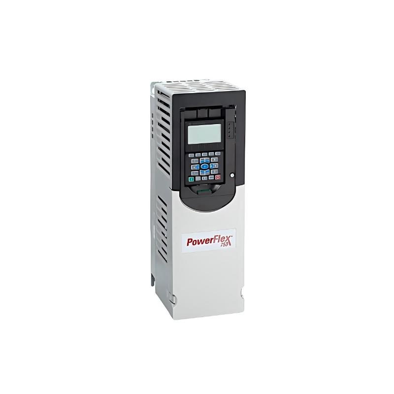
Allen-Bradley 20F14NF212JN0NNNNN — Detailed Product Specifications, Introduction, Applications, Advantages and Related Models
1. Product Overview
The 20F14NF212JN0NNNNN is a high-power industrial AC drive from the PowerFlex 753 series. It is designed for large three-phase motor applications where substantial motor current, high power capacity, adjustable speed, reliable motor control, and integration with industrial automation systems are required.
This model is designed for a 690 VAC, three-phase electrical system and provides a 212 A Normal Duty output rating. Its Normal Duty power rating is 200 kW, while its Heavy Duty rating is 171 A and 160 kW.
The drive uses a Frame 7 mechanical platform and forced-air cooling. It is an open-type drive intended for installation inside a suitable industrial enclosure or control cabinet.
The catalog number also identifies several important configuration details. The unit has DC input with precharge, a filtered configuration, the common-mode capacitor jumper installed, no internal dynamic-braking transistor, embedded I/O, and a blank/no-HIM configuration.
With a 212 A output rating and 200 kW Normal Duty capacity, the 20F14NF212JN0NNNNN is positioned near the upper end of the 690 VAC PowerFlex 753 range. It is therefore intended for substantially larger equipment than compact and medium-power variable-frequency drives.
Typical applications include large pumps, industrial fans, blowers, conveyors, rollers, mixers, agitators, process machinery, material-handling systems, and other high-power industrial equipment.
2. Brand, Family and Series
| Category | Specification |
|---|---|
| Model | 20F14NF212JN0NNNNN |
| Brand | Allen-Bradley |
| Product Family | PowerFlex 750-Series |
| Product Series | PowerFlex 753 |
| Product Type | High-Power Industrial AC Drive |
| Sub-Brand | PowerFlex |
| Drive Configuration | 753 AC Packaged Drive |
| Application Class | Industrial Architecture-Class Drive |
| Voltage Class | 690 VAC |
| Phase | Three Phase |
| Mechanical Frame | Frame 7 |
The PowerFlex 753 platform is designed for industrial applications that require more flexibility and functionality than a basic compact variable-frequency drive.
It is particularly appropriate for machinery where the drive must interact with a PLC, HMI, feedback system, industrial communication network, sensors, and other automation equipment.
The 20F14NF212JN0NNNNN represents a high-power 690 VAC configuration within this family.
3. Complete Basic Parameter Table
| Parameter | Specification |
|---|---|
| Model | 20F14NF212JN0NNNNN |
| Brand | Allen-Bradley |
| Series | PowerFlex 753 |
| Product Family | PowerFlex 750-Series |
| Product Type | AC Drive / Variable Frequency Drive |
| Voltage Rating | 690 VAC |
| Phase | 3 Phase |
| Normal Duty Current | 212 A |
| Normal Duty Power | 200 kW |
| Heavy Duty Current | 171 A |
| Heavy Duty Power | 160 kW |
| Input Type | DC Input with Precharge |
| DC Bus Class | Approximately 932 VDC |
| Frame Size | Frame 7 |
| Cooling Method | Forced Air |
| Enclosure | IP00 / NEMA/UL Open Type |
| IP20 Conversion | Available with suitable enclosure arrangement |
| Filtering | Filtered |
| CM Capacitor Jumper | Installed |
| Dynamic Braking | None |
| Internal Dynamic-Braking Transistor | No |
| HIM | Blank / No HIM |
| Embedded I/O | Yes |
| Protection | Standard Protection |
| Approx. Height | 881.5 mm class |
| Approx. Width | 430 mm class |
| Approx. Depth | 349.6 mm class |
| Approx. Dimensions | 881.5 × 430 × 349.6 mm class |
| Approx. Product Weight | Approximately 14.51 kg product-weight reference |
| Weight (kg) | Approx. 14.51 kg |
| Installation | Industrial Control Cabinet |
| Mounting | Panel / Cabinet |
| Cooling | Forced Air |
| Typical Application | Large industrial motor systems |
The electrical rating of 212 A is the most important selection parameter for the target model.
The Normal Duty rating is 200 kW, while the Heavy Duty rating is 160 kW.
The drive is intended for a 690 VAC three-phase system and uses a Frame 7 construction.
4. Electrical Rating
| Electrical Parameter | Normal Duty | Heavy Duty |
|---|---|---|
| Model | 20F14NF212JN0NNNNN | 20F14NF212JN0NNNNN |
| Voltage | 690 VAC | 690 VAC |
| Phase | 3 Phase | 3 Phase |
| Continuous Output Current | 212 A | 171 A |
| 1-Minute Overload Current | Approx. 233 A | Approx. 257 A |
| Short-Term Overload Current | Approx. 318 A | Approx. 318 A |
| Power Rating | 200 kW | 160 kW |
| Frame | 7 | 7 |
| Cooling | Forced Air | Forced Air |
| Dynamic Braking | None | None |
The 212 A Normal Duty rating provides the drive with a substantial amount of current capacity for large motors.
The corresponding 200 kW Normal Duty rating makes this model appropriate for high-power continuous-duty equipment.
For applications with heavier torque requirements, the Heavy Duty rating of 171 A / 160 kW should be considered.
5. 200 kW Normal Duty Capability
The 200 kW Normal Duty rating is one of the defining characteristics of the 20F14NF212JN0NNNNN.
A drive in this power range is typically used on equipment where the motor operates continuously or for extended periods and where the load does not exceed the applicable Normal Duty overload characteristics.
Typical examples include:
- Large centrifugal pumps.
- Large industrial fans.
- High-capacity blowers.
- Large ventilation systems.
- Continuous conveyors.
- Large process machines.
- Industrial cooling systems.
- Material-handling equipment.
The motor should not be selected based on kW alone.
The actual motor nameplate current should always be compared with the drive current rating.
6. 160 kW Heavy Duty Capability
The Heavy Duty rating is 171 A and 160 kW.
This rating is important for applications where the motor experiences greater torque demand or more demanding acceleration and overload conditions.
Potential Heavy Duty applications include:
- Heavy conveyors.
- Mixers.
- Agitators.
- High-inertia machinery.
- Material-handling equipment.
- Large rollers.
- Process machinery.
- Machinery with frequent acceleration.
Heavy Duty selection should be based on the actual motor current and machine operating cycle.
7. 690 VAC Three-Phase Operation
The 20F14NF212JN0NNNNN is designed for a 690 VAC three-phase electrical system.
This voltage class is particularly useful for large industrial motors.
Large motors can require very high current when operated at lower voltage levels.
Using a 690 VAC motor system can help manage current within the overall plant electrical distribution architecture.
This has implications for:
- Motor selection.
- Motor cables.
- Switchgear.
- Protection equipment.
- Transformers.
- Distribution panels.
- Cabinet wiring.
- Grounding.
- Electrical clearances.
The 690 VAC rating is therefore an important part of the model’s application profile.
8. DC Input with Precharge
The 20F14NF212JN0NNNNN uses a DC input with precharge configuration.
The associated DC-bus class is approximately 932 VDC.
This configuration is especially useful in systems where a DC bus is part of the overall drive architecture.
A precharge system controls the initial charging of the DC-bus capacitors.
This is important in high-power equipment because the DC bus contains substantial stored electrical energy.
The precharge process helps manage the initial charging current when the system is energized.
9. Common DC-Bus Applications
A DC-bus architecture can be useful when multiple drives or power-conversion devices are integrated into one electrical system.
A simplified architecture may look like:
AC Power System → Common DC Bus → Drive Power Sections → Motors
This type of architecture can be advantageous when the machine has several motors that operate together.
For example, a large production line may contain:
- Main conveyor motors.
- Roller motors.
- Cooling fans.
- Pumps.
- Auxiliary motors.
- Material-handling motors.
A common DC-bus architecture can provide flexibility when the overall machine power system has been designed accordingly.
10. Dynamic Braking Configuration
The exact catalog number 20F14NF212JN0NNNNN specifies:
Dynamic Braking: None.
It also specifies:
No internal dynamic-braking transistor.
This distinction is important.
The drive does not contain the internal dynamic-braking switching transistor associated with certain other configurations.
Therefore, the user should not assume that a dynamic-braking resistor can simply be connected directly to the drive.
If the machine generates significant regenerative energy during deceleration, the complete braking strategy must be designed separately.
11. Braking Considerations for Large Motors
Large motors can store significant mechanical energy.
This becomes particularly important when the driven machine has:
- Large rotating inertia.
- High operating speed.
- Heavy material loads.
- Frequent stops.
- Rapid acceleration and deceleration.
- Long conveyors.
- Large rollers.
- Flywheels.
- High-inertia fans.
During deceleration, the motor can operate as a generator.
The resulting energy can return to the DC bus.
If the energy cannot be absorbed or returned to the electrical system, the DC-bus voltage can increase.
Possible engineering approaches include:
- Increasing deceleration time.
- Using appropriate external braking equipment.
- Using regenerative power equipment.
- Using mechanical braking.
- Changing the drive configuration.
- Adjusting the machine operating sequence.
The correct approach depends on the machine’s actual inertia, speed and stopping requirements.
12. Frame 7 Mechanical Construction
The 20F14NF212JN0NNNNN uses a Frame 7 design.
Frame 7 is intended for high-power drive applications.
The approximate mechanical envelope is in the following range:
Height: approximately 881.5 mm class.
Width: approximately 430 mm class.
Depth: approximately 349.6 mm class.
Overall dimensions: approximately 881.5 × 430 × 349.6 mm class.
| Mechanical Parameter | Specification |
|---|---|
| Model | 20F14NF212JN0NNNNN |
| Frame | Frame 7 |
| Height | Approx. 881.5 mm class |
| Width | Approx. 430 mm class |
| Depth | Approx. 349.6 mm class |
| Approx. Dimensions | 881.5 × 430 × 349.6 mm class |
| Enclosure | IP00 / NEMA/UL Open Type |
| Cooling | Forced Air |
| Mounting | Panel / Cabinet |
| Weight (kg) | Approx. 14.51 kg |
| Installation | Industrial Enclosure |
The exact mechanical arrangement can vary according to the physical configuration and documentation revision.
For cabinet fabrication, lifting equipment selection, shipping calculations and final installation, the exact dimensional drawing for the supplied unit should be treated as the controlling reference.
13. Dimensions and Weight
| Specification | Value |
|---|---|
| Model | 20F14NF212JN0NNNNN |
| Frame Size | Frame 7 |
| Approx. Height | 881.5 mm |
| Approx. Width | 430 mm |
| Approx. Depth | 349.6 mm |
| Approx. Overall Size | 881.5 × 430 × 349.6 mm |
| Weight (kg) | Approx. 14.51 kg |
| Enclosure Type | Open Type |
| Cooling | Forced Air |
| Cabinet Installation | Required |
| Service Clearance | Required |
| Ventilation Clearance | Required |
The 14.51 kg figure should be treated as a product-weight reference rather than a shipping-package weight.
Packaging, mounting hardware, optional components and cabinet accessories can add additional weight to the complete installed system.
14. Open-Type Enclosure
The 20F14NF212JN0NNNNN is an open-type drive.
The standard enclosure classification is associated with IP00 / NEMA/UL Open Type construction.
This means that the drive is normally installed inside an appropriate enclosure.
The external cabinet may be selected according to the environmental conditions of the installation.
The enclosure may need to provide protection against:
- Dust.
- Moisture.
- Oil.
- Foreign objects.
- Accidental contact.
- Chemical contamination.
- Mechanical impact.
The complete enclosure design must also account for cooling and ventilation.
15. IP20 / Type 1 Conversion
A suitable enclosure kit can be used with applicable Frame 7 configurations to achieve a more protected enclosure arrangement.
This can be useful when the final machine requires additional touch protection.
However, the final enclosure rating depends on the complete installation.
Cable entries, cabinet doors, ventilation openings, filters and other openings must all be considered when establishing the final protection level.
16. Forced-Air Cooling
The drive uses forced-air cooling.
At a 200 kW Normal Duty rating, thermal management becomes a major engineering consideration.
The cabinet should have a well-designed airflow path.
The cooling air must not be obstructed by:
- Cable bundles.
- Cabinet partitions.
- Filters.
- Other electrical components.
- Structural members.
- Incorrectly positioned accessories.
| Cooling Parameter | Recommendation |
|---|---|
| Model | 20F14NF212JN0NNNNN |
| Cooling Method | Forced Air |
| Cabinet Ventilation | Required |
| Airflow | Must remain unobstructed |
| Fan Maintenance | Required |
| Air Filter Maintenance | Required where applicable |
| Cabinet Temperature | Must remain within allowable limits |
| Heat Dissipation | Must be considered |
| Multiple Drives | Combined thermal load must be calculated |
Poor ventilation can increase internal temperature and place additional stress on electronic components.
For a large industrial installation, cooling should therefore be considered during the cabinet design stage rather than after the cabinet has already been constructed.
17. Filtering Configuration
The target model is supplied with a filtered configuration.
The common-mode capacitor jumper is also installed.
These characteristics affect the electrical behavior of the drive and should be considered when planning:
- Grounding.
- Motor cable routing.
- Cable shielding.
- EMC.
- Control wiring.
- Motor insulation.
- Long motor cables.
- Sensitive instrumentation.
Correct installation practices are especially important when the drive is operating close to sensitive control equipment.
18. Embedded I/O
The PowerFlex 753 architecture provides embedded I/O for basic drive integration.
This allows the drive to exchange control and status signals with the surrounding machine.
Typical signals can include:
- Start.
- Stop.
- Enable.
- Run command.
- Speed reference.
- Fault status.
- Drive status.
- Digital inputs.
- Digital outputs.
- Analog signals.
Embedded I/O can reduce the need for additional external interface components for basic machine-control functions.
19. Human Interface Configuration
The catalog number specifies:
Blank / No HIM.
This means that the unit is not configured with a door-mounted Human Interface Module.
For a machine that requires a local operator interface, an appropriate interface arrangement can be considered separately.
A blank configuration can be useful when the drive is controlled primarily through:
- PLC.
- HMI.
- Industrial network.
- Remote control station.
- Machine controller.
This configuration can also make sense when the drive is installed inside a dedicated electrical cabinet where local keypad operation is not part of the normal operating procedure.
20. Motor Control
The PowerFlex 753 platform supports multiple motor-control strategies depending on the application and selected configuration.
Possible approaches include:
- Volts-per-Hertz control.
- Sensorless vector control.
- Vector control.
- Encoder feedback.
- Speed control.
- Torque control.
- Position-related control functions.
The correct control mode depends on the machine.
A large centrifugal pump generally has very different control requirements from a high-inertia conveyor or precision production roller.
21. Application — Large Pumps
Large pumps are a natural application for the 20F14NF212JN0NNNNN.
Examples include:
- Water circulation pumps.
- Cooling-water pumps.
- Industrial process pumps.
- Transfer pumps.
- Large water-treatment pumps.
- Utility pumps.
- Industrial fluid systems.
Variable-speed operation can allow the pump to operate according to actual process requirements.
Instead of running continuously at one fixed speed, the motor speed can be adjusted according to:
- Flow demand.
- Pressure requirement.
- Process conditions.
- Production rate.
- System demand.
This can improve operational flexibility and may reduce unnecessary mechanical and electrical stress.
22. Application — Large Fans
Industrial fans can require motors in the 100 kW to 200 kW class and above.
Typical applications include:
- Furnace fans.
- Process ventilation.
- Industrial exhaust.
- Large cooling systems.
- Combustion-air systems.
- Dust collection.
- Industrial HVAC.
The drive can adjust fan speed to match the actual airflow requirement.
This can be especially useful when process demand changes throughout the production cycle.
23. Application — Large Blowers
Large blowers can require substantial motor power.
Applications include:
- Pneumatic conveying.
- Process air.
- Wastewater aeration.
- Industrial drying.
- Dust collection.
- Furnace systems.
- Chemical processes.
- Manufacturing processes.
The 200 kW Normal Duty capability gives the drive sufficient capacity for many large blower systems.
24. Application — Heavy Conveyors
Heavy conveyors are another important application.
Large conveyors may experience significant torque requirements during startup.
The drive can provide controlled acceleration and speed regulation.
Potential applications include:
- Mining.
- Bulk material handling.
- Aggregate processing.
- Steel plants.
- Cement plants.
- Large manufacturing facilities.
- Logistics systems.
Important conveyor design factors include:
- Starting torque.
- Conveyor inertia.
- Load distribution.
- Acceleration time.
- Deceleration time.
- Regenerative energy.
- Mechanical braking.
Because the JN configuration has no internal dynamic-braking transistor, the stopping system should be engineered separately where rapid braking is required.
25. Application — Rollers
Large rollers are used in many continuous-production industries.
Typical applications include:
- Steel processing.
- Paper manufacturing.
- Printing.
- Packaging.
- Web handling.
- Material processing.
- Continuous production lines.
Roller systems may require precise speed control and synchronization.
When several motors operate together, communication and feedback functions can help maintain coordinated operation.
26. Application — Mixers
Large mixers can present a difficult motor load.
The mechanical load can change as material is introduced or removed.
Starting torque can also be considerably higher than the steady-state running torque.
Applications include:
- Chemical processing.
- Food processing.
- Industrial materials.
- Batch processing.
- Manufacturing.
- Process tanks.
For mixer applications, Heavy Duty selection should be considered if the machine requires high starting or continuous torque.
27. Application — Agitators
Large agitators are often used in tanks and process vessels.
Applications include:
- Chemical processing.
- Water treatment.
- Industrial blending.
- Process-fluid systems.
- Manufacturing.
- Batch processing.
The drive can provide controlled speed and acceleration while allowing the agitator to become part of a larger automated process.
28. Application — Material Handling
High-power material-handling systems can use multiple motors.
The PowerFlex 753 platform is suitable for installations where several drives must operate together.
Applications include:
- Conveyors.
- Transfer systems.
- Bulk material handling.
- Production transport.
- Industrial logistics.
- Sorting systems.
- Processing equipment.
The ability to integrate motor-control functions into a PLC-based architecture is particularly useful in these applications.
29. Application — Process Machinery
The 20F14NF212JN0NNNNN can be used in large process machines requiring adjustable speed.
Potential equipment includes:
- Large production machines.
- Process lines.
- Manufacturing systems.
- Industrial auxiliaries.
- Large pumps.
- Fans.
- Blowers.
- Rollers.
- Mixers.
The high current rating makes the drive appropriate where smaller PowerFlex configurations no longer provide sufficient motor capacity.
30. Major Product Advantages
30.1 212 A Output Capacity
The biggest electrical advantage of this model is its 212 A Normal Duty output rating.
This provides considerable current capacity for large industrial motors.
30.2 200 kW Normal Duty
The 200 kW Normal Duty rating makes this model suitable for very large continuous-duty motor applications.
This places it near the upper end of the 690 VAC PowerFlex 753 range.
30.3 171 A / 160 kW Heavy Duty
The Heavy Duty rating provides 171 A and 160 kW capability.
This is valuable for applications with greater torque demand or more demanding operating cycles.
30.4 690 VAC Voltage Class
The 690 VAC rating makes the model appropriate for large industrial motor systems.
It is especially useful where large motors are already designed around a 690 VAC electrical system.
30.5 Frame 7 Construction
The Frame 7 platform is designed for high-power operation.
It provides the mechanical and thermal architecture needed for a drive of this capacity.
30.6 DC Input with Precharge
The DC input configuration provides flexibility for common-bus systems.
The precharge arrangement is particularly important for large DC-bus capacitance.
30.7 Embedded I/O
Embedded I/O simplifies basic machine integration.
This can reduce the amount of additional interface hardware required.
30.8 Expandable Architecture
The PowerFlex 753 platform provides options for expanding the drive according to the application’s requirements.
This can include communication, feedback, I/O and other functions.
30.9 Industrial Automation Integration
The drive can be integrated into a larger PLC and HMI system.
This allows motor control to become part of the overall machine automation architecture.
31. Advantages for Large Industrial Systems
The 20F14NF212JN0NNNNN is especially valuable where the motor system is too large for compact drives.
Its combination of:
- 212 A current capacity.
- 200 kW Normal Duty.
- 171 A Heavy Duty.
- 160 kW Heavy Duty.
- 690 VAC operation.
- Frame 7 construction.
- Embedded I/O.
- Expandable architecture.
makes it suitable for substantial industrial equipment.
32. Advantages for System Integrators
For system integrators, the PowerFlex 753 platform offers a standardized approach to large motor control.
A typical system can include:
PLC → Industrial Network → PowerFlex 753 → Motor
The drive can provide information back to the controller such as:
- Actual speed.
- Output current.
- Drive status.
- Fault status.
- Warning status.
- Operating condition.
- Command confirmation.
This makes it easier to integrate the drive into a larger automation system.
33. Advantages for Maintenance
A standardized industrial drive platform can simplify maintenance.
Typical maintenance activities include:
- Cooling-fan inspection.
- Cabinet ventilation inspection.
- Air-filter inspection.
- Power-terminal inspection.
- Grounding inspection.
- Motor-cable inspection.
- Communication inspection.
- Parameter verification.
- Fault-history analysis.
The maintenance team can use the same general troubleshooting approach across multiple PowerFlex 753 installations.
34. Complete Technical Specification
| Technical Parameter | 20F14NF212JN0NNNNN |
|---|---|
| Brand | Allen-Bradley |
| Family | PowerFlex 750-Series |
| Series | PowerFlex 753 |
| Product Type | Industrial AC Drive |
| Voltage | 690 VAC |
| Phase | 3 Phase |
| ND Current | 212 A |
| ND Power | 200 kW |
| HD Current | 171 A |
| HD Power | 160 kW |
| ND 1-Minute Current | Approx. 233 A |
| ND 3-Second Current | Approx. 318 A |
| HD 1-Minute Current | Approx. 257 A |
| HD 3-Second Current | Approx. 318 A |
| Input | DC Input with Precharge |
| DC Bus Class | Approx. 932 VDC |
| Frame | 7 |
| Cooling | Forced Air |
| Enclosure | IP00 / NEMA/UL Open Type |
| Filtering | Filtered |
| CM Jumper | Installed |
| Dynamic Braking | None |
| Internal DB Transistor | None |
| HIM | Blank / No HIM |
| Embedded I/O | Yes |
| Protection | Standard |
| Approx. Height | 881.5 mm class |
| Approx. Width | 430 mm class |
| Approx. Depth | 349.6 mm class |
| Approx. Dimensions | 881.5 × 430 × 349.6 mm class |
| Weight (kg) | Approx. 14.51 kg |
| Cooling Type | Forced Air |
| Mounting | Cabinet / Panel |
| Typical Motor Power | Up to 200 kW ND |
| Typical Heavy-Duty Motor Power | Up to 160 kW HD |
35. Five Recommended Same-Series Models
The following models are closely related 690 VAC PowerFlex 753 configurations.
They are useful when selecting a drive according to motor current and power requirements.
| Model | Series | Voltage | ND Current | ND Power | HD Current | HD Power | Frame | Dynamic Braking | Approx. Dimensions | Weight (kg) |
|---|---|---|---|---|---|---|---|---|---|---|
| 20F14NF119JN0NNNNN | PowerFlex 753 | 690 VAC | 119 A | 110 kW | 98 A | 90 kW | 6 | None | Approx. 665.5 × 308 × 346.4 mm class | Approx. 14.5 |
| 20F14NF142JN0NNNNN | PowerFlex 753 | 690 VAC | 142 A | 132 kW | 119 A | 110 kW | 6 | None | Approx. 665.5 × 308 × 346.4 mm class | Approx. 14.5 |
| 20F14NF171JN0NNNNN | PowerFlex 753 | 690 VAC | 171 A | 160 kW | 142 A | 132 kW | 7 | None | Approx. 881.5 × 430 × 349.6 mm class | Approx. 14.5 |
| 20F14NF212JN0NNNNN | PowerFlex 753 | 690 VAC | 212 A | 200 kW | 171 A | 160 kW | 7 | None | Approx. 881.5 × 430 × 349.6 mm class | Approx. 14.51 |
| 20F14NF263JN0NNNNN | PowerFlex 753 | 690 VAC | 263 A | 250 kW | 212 A | 200 kW | 7 | None | Approx. 881.5 × 430 × 349.6 mm class | Approx. 14.5 |
These five models provide a useful power progression.
The 119 A model is suitable for applications around 110 kW Normal Duty.
The 142 A model increases the Normal Duty capability to 132 kW.
The 171 A model provides 160 kW Normal Duty.
The target 212 A model increases this to 200 kW Normal Duty.
The 263 A model provides a further step to 250 kW Normal Duty.
36. Same-Series Comparison
| Model | ND Current | ND Power | HD Current | HD Power | Frame | Voltage |
|---|---|---|---|---|---|---|
| 20F14NF119JN0NNNNN | 119 A | 110 kW | 98 A | 90 kW | 6 | 690 VAC |
| 20F14NF142JN0NNNNN | 142 A | 132 kW | 119 A | 110 kW | 6 | 690 VAC |
| 20F14NF171JN0NNNNN | 171 A | 160 kW | 142 A | 132 kW | 7 | 690 VAC |
| 20F14NF212JN0NNNNN | 212 A | 200 kW | 171 A | 160 kW | 7 | 690 VAC |
| 20F14NF263JN0NNNNN | 263 A | 250 kW | 212 A | 200 kW | 7 | 690 VAC |
This progression clearly shows the position of the 212 A model.
It sits between the 171 A / 160 kW configuration and the 263 A / 250 kW configuration.
For a motor requiring approximately 200 kW Normal Duty, the 212 A model is the natural high-power choice within this group.
37. 20F14NF171JN0NNNNN vs. 20F14NF212JN0NNNNN
| Parameter | 20F14NF171JN0NNNNN | 20F14NF212JN0NNNNN |
|---|---|---|
| Voltage | 690 VAC | 690 VAC |
| ND Current | 171 A | 212 A |
| ND Power | 160 kW | 200 kW |
| HD Current | 142 A | 171 A |
| HD Power | 132 kW | 160 kW |
| Frame | 7 | 7 |
| Cooling | Forced Air | Forced Air |
| Input | DC + Precharge | DC + Precharge |
| Filtering | Filtered | Filtered |
| CM Jumper | Installed | Installed |
| Dynamic Braking | None | None |
| Approx. Dimensions | 881.5 × 430 × 349.6 mm class | 881.5 × 430 × 349.6 mm class |
| Weight (kg) | Approx. 14.5 | Approx. 14.51 |
The main difference is electrical capacity.
The target model provides 41 A more Normal Duty current than the 171 A model.
Normal Duty power increases from 160 kW to 200 kW.
Heavy Duty power increases from 132 kW to 160 kW.
This makes the 212 A model a logical choice when the 171 A configuration does not provide enough current or power margin.
38. 20F14NF142JN0NNNNN vs. 20F14NF212JN0NNNNN
| Parameter | 20F14NF142JN0NNNNN | 20F14NF212JN0NNNNN |
|---|---|---|
| Voltage | 690 VAC | 690 VAC |
| ND Current | 142 A | 212 A |
| ND Power | 132 kW | 200 kW |
| HD Current | 119 A | 171 A |
| HD Power | 110 kW | 160 kW |
| Frame | 6 | 7 |
| Cooling | Forced Air | Forced Air |
| Dynamic Braking | None | None |
| Approx. Dimensions | 665.5 × 308 × 346.4 mm class | 881.5 × 430 × 349.6 mm class |
| Weight (kg) | Approx. 14.5 | Approx. 14.51 |
The target model provides a substantial increase in power capability.
Normal Duty power rises from 132 kW to 200 kW.
Heavy Duty power rises from 110 kW to 160 kW.
The mechanical frame also changes from Frame 6 to Frame 7.
39. 20F14NF263JN0NNNNN Comparison
| Parameter | 20F14NF212JN0NNNNN | 20F14NF263JN0NNNNN |
|---|---|---|
| Voltage | 690 VAC | 690 VAC |
| ND Current | 212 A | 263 A |
| ND Power | 200 kW | 250 kW |
| HD Current | 171 A | 212 A |
| HD Power | 160 kW | 200 kW |
| Frame | 7 | 7 |
| Cooling | Forced Air | Forced Air |
| Dynamic Braking | None | None |
| Approx. Dimensions | 881.5 × 430 × 349.6 mm class | 881.5 × 430 × 349.6 mm class |
| Weight (kg) | Approx. 14.51 | Approx. 14.5 |
The 263 A configuration should be considered when the motor requires more than the 212 A capacity.
The 212 A model is therefore an important intermediate selection between 171 A and 263 A.
40. Five Same-Brand Popular or Related Models
The following five models are useful for comparing different drive sizes and product families within the same brand.
| Model | Series | Voltage Class | Current Class | Approx. Power Class | Cooling | Product Position | Approx. Dimensions | Weight (kg) |
|---|---|---|---|---|---|---|---|---|
| 25B-D017N104 | PowerFlex 525 | 480 VAC Class | 17 A | Approx. 7.5 kW | Air Cooled | Compact industrial drive | Approx. 200 × 300 × 180 mm | Approx. 5 |
| 25B-D024N104 | PowerFlex 525 | 480 VAC Class | 24 A | Approx. 11 kW | Air Cooled | Compact industrial drive | Approx. 230 × 350 × 190 mm | Approx. 6–8 |
| 25B-D043N114 | PowerFlex 525 | 480 VAC Class | 43 A | Approx. 22 kW | Air Cooled | Medium industrial drive | Approx. 250 × 400 × 220 mm | Approx. 10–15 |
| 20F11NC043JA0NNNNN | PowerFlex 753 | 480 VAC Class | 43 A | Approx. 22 kW | Air Cooled | Architecture-class drive | Frame dependent | Approx. 30–45 |
| 20G11NC043JA0NNNNN | PowerFlex 755 | 480 VAC Class | 43 A | Approx. 22 kW | Air Cooled | Advanced architecture drive | Frame dependent | Approx. 30–45 |
These are related models rather than direct electrical replacements.
The 25B models are much smaller and are normally used for lower-power machinery.
The PowerFlex 753 models are designed for larger industrial applications.
The PowerFlex 755 family is another advanced industrial-drive option.
41. Same-Brand Model Comparison
| Feature | 25B-D017N104 | 25B-D024N104 | 25B-D043N114 | 20F11NC043JA0NNNNN | 20G11NC043JA0NNNNN |
|---|---|---|---|---|---|
| Series | PowerFlex 525 | PowerFlex 525 | PowerFlex 525 | PowerFlex 753 | PowerFlex 755 |
| Voltage Class | 480 VAC | 480 VAC | 480 VAC | 480 VAC | 480 VAC |
| Current Class | 17 A | 24 A | 43 A | 43 A | 43 A |
| Approx. Power | 7.5 kW | 11 kW | 22 kW | 22 kW | 22 kW |
| Product Size | Compact | Compact | Medium | Large | Large |
| Typical Application | Small/medium machines | Small/medium machines | Medium machines | Large machinery | Advanced machinery |
| Approx. Dimensions | 200 × 300 × 180 mm | 230 × 350 × 190 mm | 250 × 400 × 220 mm | Frame dependent | Frame dependent |
| Weight (kg) | Approx. 5 | Approx. 6–8 | Approx. 10–15 | Approx. 30–45 | Approx. 30–45 |
These models demonstrate the range of products available for different motor sizes.
The target 20F14NF212JN0NNNNN is substantially larger in electrical capacity and is designed specifically for high-power 690 VAC motor systems.
42. PowerFlex 525 and PowerFlex 753 Comparison
| Characteristic | PowerFlex 525 | PowerFlex 753 |
|---|---|---|
| Product Position | Compact Industrial Drive | Architecture-Class Industrial Drive |
| Typical Motor Size | Small to Medium | Medium to Very Large |
| Physical Size | Compact | Large |
| 690 VAC Availability | Not the primary class | Yes |
| Embedded I/O | Yes | Yes |
| Modular Expansion | More Limited | Extensive |
| Feedback Options | Application Dependent | Available |
| Communication | Available | Extensive Options |
| Cabinet Requirement | Smaller | Larger |
| Main Target | Compact Machinery | Large Industrial Machinery |
The PowerFlex 525 is useful where compact size and moderate power are the primary requirements.
The PowerFlex 753 becomes more attractive when the motor becomes larger or the machine requires more sophisticated integration.
43. PowerFlex 753 and PowerFlex 755 Comparison
| Feature | PowerFlex 753 | PowerFlex 755 |
|---|---|---|
| High-Power Motor Control | Yes | Yes |
| Speed Control | Yes | Yes |
| Torque Control | Yes | Yes |
| Modular Architecture | Yes | Yes |
| Feedback Options | Available | Available |
| Communication Options | Available | Extensive |
| I/O Expansion | Available | Available |
| Safety Options | Available with suitable configuration | Available with suitable configuration |
| Typical Application | Industrial Machinery | Advanced Industrial Machinery |
| Target Model | 20F14NF212JN0NNNNN | Related alternative |
The PowerFlex 753 platform is well suited to large industrial machines.
The PowerFlex 755 family can be considered where a more advanced drive architecture or more sophisticated control functionality is required.
44. Motor Selection Parameters
The motor must be selected using actual nameplate information.
| Motor Parameter | Selection Requirement |
|---|---|
| Model | 20F14NF212JN0NNNNN |
| Motor Voltage | Compatible with 690 VAC system |
| Motor Current | Must be within applicable drive rating |
| Motor Power | Compare with 200 kW ND / 160 kW HD |
| Motor Frequency | Verify application requirement |
| Motor Speed | Verify required operating range |
| Starting Torque | Evaluate |
| Continuous Torque | Evaluate |
| Peak Torque | Evaluate |
| Motor Type | Verify compatibility |
| Feedback | Determine whether feedback is required |
| Braking | Evaluate regenerative energy |
| Motor Cable | Evaluate cable length and routing |
| Environment | Check temperature, dust, moisture and vibration |
The drive should be selected based on motor current rather than simply matching motor kW.
This is especially important for large motors because efficiency, power factor, voltage and motor construction affect current.
45. Why Current Rating Matters
A motor’s kW rating alone does not completely define the electrical requirements.
Two motors with the same nominal power can have different current requirements.
Factors include:
- Efficiency.
- Power factor.
- Voltage.
- Motor construction.
- Speed.
- Frequency.
- Operating temperature.
- Duty class.
For the target model, the most important electrical selection figure is therefore the 212 A Normal Duty current rating.
46. Application Selection Table
| Application | Suitability | Important Consideration |
|---|---|---|
| Large centrifugal pump | Excellent | Normal Duty |
| Large industrial fan | Excellent | Normal Duty |
| Large blower | Excellent | Normal Duty / airflow |
| Heavy conveyor | Excellent | Starting torque |
| Large roller | Excellent | Speed and inertia |
| Large mixer | Very Good | Starting torque |
| Agitator | Very Good | Torque profile |
| Process machinery | Excellent | Automation integration |
| Material handling | Excellent | Acceleration and deceleration |
| High-inertia machine | Good with appropriate braking design | Regenerative energy |
| Rapid-cycle equipment | Application dependent | Braking and thermal load |
| Large production line | Excellent | Multi-drive coordination |
47. Typical Industrial Control Architecture
A large machine can use the following architecture:
PLC / Controller → Industrial Network → PowerFlex 753 → 690 VAC Motor → Mechanical Load
An HMI may be connected to the PLC:
HMI → PLC → Drive → Motor
Feedback can also be integrated:
Encoder → Drive Feedback Interface → Motor Control
Where required, external braking or regenerative equipment can be added as part of the complete power architecture.
48. Typical Industries
| Industry | Typical Application |
|---|---|
| Mining | Heavy conveyors and material handling |
| Metals | Large rollers and process equipment |
| Paper | Rollers and production lines |
| Chemical Processing | Pumps, mixers and agitators |
| Water Treatment | Pumps and blowers |
| Manufacturing | Large production machinery |
| Food Processing | Mixers and conveyors |
| Industrial HVAC | Large fans and blowers |
| Utilities | Pumps and auxiliary equipment |
| Material Handling | Conveyors and transfer systems |
| Process Industry | Pumps, fans, blowers and mixers |
49. Installation Considerations
The physical dimensions of the Frame 7 drive should be included in the cabinet design from the beginning.
The approximate envelope is:
881.5 mm × 430 mm × 349.6 mm.
The product-weight reference is approximately:
14.51 kg.
The actual cabinet design must also provide space for:
- Power cables.
- Motor cables.
- DC-bus connections.
- Control wiring.
- Communication modules.
- Grounding.
- Ventilation.
- Maintenance.
- Service access.
The cabinet should not be designed around the drive’s external dimensions alone.
Additional installation clearance is required.
50. Electrical Installation Considerations
A high-power 690 VAC drive requires careful electrical planning.
The installation should consider:
- Input power.
- DC-bus connections.
- Motor output wiring.
- Grounding.
- Protection.
- Control wiring.
- Communication wiring.
- Shielding.
- Cable separation.
- Motor insulation.
- EMC.
The 690 VAC voltage class means that the electrical installation should be treated as a high-power industrial system.
51. Thermal Design
The 200 kW power class makes thermal design especially important.
The cabinet designer should calculate the combined heat load from:
- The drive.
- Cooling equipment.
- Contactors.
- Transformers.
- Power supplies.
- Other drives.
- Control equipment.
If multiple high-power drives are installed in one cabinet, the combined thermal load must be considered.
Airflow should be arranged so that hot exhaust air does not circulate back into the drive’s cooling intake.
52. Maintenance Recommendations
A preventive-maintenance program should include:
- Cooling fan inspection.
- Airflow inspection.
- Cabinet filter inspection.
- Power-terminal inspection.
- Grounding inspection.
- Motor-cable inspection.
- Communication inspection.
- Fault-history review.
- Parameter verification.
- Temperature monitoring.
Dust and contamination should be controlled because they can restrict airflow and contribute to thermal problems.
Loose power connections should also be identified and corrected as part of normal maintenance.
53. Product Advantages at a Glance
| Advantage | Practical Benefit |
|---|---|
| 212 A Output | Supports very large industrial motors |
| 200 kW Normal Duty | High continuous-power capability |
| 171 A Heavy Duty | Supports demanding torque applications |
| 160 kW Heavy Duty | Suitable for substantial heavy-duty motors |
| 690 VAC | Designed for large high-voltage motor systems |
| Frame 7 | High-power industrial construction |
| Forced-Air Cooling | Suitable for high-power applications |
| DC Input with Precharge | Supports DC-bus architectures |
| Filtered Configuration | Helps manage electrical-noise considerations |
| CM Jumper Installed | Defined common-mode configuration |
| Embedded I/O | Simplifies basic machine integration |
| Expandable Architecture | Allows application-specific expansion |
| Communication Options | Supports automation integration |
| Feedback Options | Supports advanced motor control |
| No Internal DB Transistor | Suitable where internal dynamic braking is not required |
| PowerFlex 753 Platform | Provides a standardized industrial drive architecture |
54. Five Same-Series Models — Detailed Recommendation
| Model | Voltage | ND Current | ND Power | HD Current | HD Power | Frame | Cooling | Dynamic Braking | Approx. Dimensions | Weight (kg) |
|---|---|---|---|---|---|---|---|---|---|---|
| 20F14NF119JN0NNNNN | 690 VAC | 119 A | 110 kW | 98 A | 90 kW | 6 | Forced Air | None | 665.5 × 308 × 346.4 mm class | Approx. 14.5 |
| 20F14NF142JN0NNNNN | 690 VAC | 142 A | 132 kW | 119 A | 110 kW | 6 | Forced Air | None | 665.5 × 308 × 346.4 mm class | Approx. 14.5 |
| 20F14NF171JN0NNNNN | 690 VAC | 171 A | 160 kW | 142 A | 132 kW | 7 | Forced Air | None | 881.5 × 430 × 349.6 mm class | Approx. 14.5 |
| 20F14NF212JN0NNNNN | 690 VAC | 212 A | 200 kW | 171 A | 160 kW | 7 | Forced Air | None | 881.5 × 430 × 349.6 mm class | Approx. 14.51 |
| 20F14NF263JN0NNNNN | 690 VAC | 263 A | 250 kW | 212 A | 200 kW | 7 | Forced Air | None | 881.5 × 430 × 349.6 mm class | Approx. 14.5 |
These five models form a useful high-power selection group.
The 119 A configuration is intended for approximately 110 kW Normal Duty.
The 142 A configuration increases capacity to 132 kW.
The 171 A configuration reaches 160 kW.
The target 212 A configuration reaches 200 kW.
The 263 A configuration increases the Normal Duty rating again to 250 kW.
55. Five Same-Brand Popular or Related Models
| Model | Series | Voltage Class | Current | Approx. Power | Cooling | Typical Position | Approx. Dimensions | Weight (kg) |
|---|---|---|---|---|---|---|---|---|
| 25B-D017N104 | PowerFlex 525 | 480 VAC Class | 17 A | Approx. 7.5 kW | Air Cooled | Compact machine drive | Approx. 200 × 300 × 180 mm | Approx. 5 |
| 25B-D024N104 | PowerFlex 525 | 480 VAC Class | 24 A | Approx. 11 kW | Air Cooled | Compact machine drive | Approx. 230 × 350 × 190 mm | Approx. 6–8 |
| 25B-D043N114 | PowerFlex 525 | 480 VAC Class | 43 A | Approx. 22 kW | Air Cooled | Medium machine drive | Approx. 250 × 400 × 220 mm | Approx. 10–15 |
| 20F11NC043JA0NNNNN | PowerFlex 753 | 480 VAC Class | 43 A | Approx. 22 kW | Air Cooled | Industrial architecture drive | Frame dependent | Approx. 30–45 |
| 20G11NC043JA0NNNNN | PowerFlex 755 | 480 VAC Class | 43 A | Approx. 22 kW | Air Cooled | Advanced industrial drive | Frame dependent | Approx. 30–45 |
These five products are useful as related products because they cover different power levels and drive architectures.
They are not direct electrical replacements for the 690 VAC 212 A model.
The voltage class, current rating, motor power, overload requirement and complete application should always be checked before making a substitution.
56. Selection Guide by Motor Power
| Motor Requirement | Recommended Model Direction |
|---|---|
| Approx. 110 kW ND | 20F14NF119JN0NNNNN |
| Approx. 132 kW ND | 20F14NF142JN0NNNNN |
| Approx. 160 kW ND | 20F14NF171JN0NNNNN |
| Approx. 200 kW ND | 20F14NF212JN0NNNNN |
| Approx. 250 kW ND | 20F14NF263JN0NNNNN |
| Approx. 110 kW HD | 20F14NF142JN0NNNNN |
| Approx. 132 kW HD | 20F14NF171JN0NNNNN |
| Approx. 160 kW HD | 20F14NF212JN0NNNNN |
| Approx. 200 kW HD | 20F14NF263JN0NNNNN |
This progression makes the 20F14NF212JN0NNNNN particularly useful for systems where the motor requires approximately 200 kW Normal Duty or 160 kW Heavy Duty capacity.
57. Why the 212 A Model Is Important
The 212 A model represents a major step in the 690 VAC PowerFlex 753 range.
Its main electrical ratings are:
212 A Normal Duty.
200 kW Normal Duty.
171 A Heavy Duty.
160 kW Heavy Duty.
This makes it suitable for motors substantially larger than those served by the 142 A and 171 A configurations.
It also remains within the Frame 7 high-power platform.
58. Frame 7 Advantages
Frame 7 is intended for high-power applications.
The larger frame provides an appropriate physical platform for:
- High-current power sections.
- High-power electrical connections.
- Larger cooling requirements.
- High-power motor wiring.
- Larger industrial cabinet installations.
The Frame 7 configuration should therefore be considered as part of the overall machine architecture rather than simply a larger version of a compact drive.
59. Braking Requirements for High-Inertia Machines
Large industrial machines can have substantial stored energy.
This is particularly true for:
- Heavy conveyors.
- Large rollers.
- High-speed fans.
- Flywheel systems.
- Large mixers.
- Rotating process equipment.
The engineer should determine:
- Maximum motor speed.
- Rotating inertia.
- Load inertia.
- Required stopping time.
- Number of stops per hour.
- Regenerative energy.
- Required braking torque.
- Mechanical brake requirements.
Because the target configuration has no internal dynamic-braking transistor, these requirements must be addressed separately.
60. Product Advantages for Pump Applications
For large pumps, the drive provides adjustable speed while supporting very high motor power.
The pump can be operated according to process requirements rather than simply running continuously at one fixed speed.
Potential benefits include:
- Adjustable flow.
- Controlled acceleration.
- Controlled stopping.
- Process integration.
- Remote monitoring.
- Reduced mechanical shock.
The exact operating strategy depends on the pump and process.
61. Product Advantages for Fan Applications
For large fans and blowers, the ability to vary speed can provide significant operational flexibility.
The drive can respond to changing airflow requirements.
Applications can include:
- Exhaust.
- Ventilation.
- Furnace systems.
- Cooling.
- Combustion air.
- Dust collection.
The 200 kW Normal Duty rating makes the model appropriate for very large fan systems.
62. Product Advantages for Conveyor Applications
Large conveyors benefit from controlled acceleration.
Instead of applying full motor torque immediately, the drive can control the acceleration profile.
This can reduce mechanical stress on:
- Belts.
- Gearboxes.
- Couplings.
- Shafts.
- Bearings.
- Material loads.
For heavy conveyor systems, the braking system must also be evaluated carefully.
63. Product Advantages for Process Machinery
Large process machines can benefit from both high motor capacity and automation integration.
The drive can operate as a dedicated motor-control element within the machine’s control architecture.
The PLC can manage the process while the drive handles motor-control functions.
This division can simplify the overall control structure.
64. Typical High-Power System Architecture
A representative system can be arranged as:
690 VAC Power Supply
↓
Protection and Power Distribution
↓
20F14NF212JN0NNNNN
↓
690 VAC Motor
↓
Mechanical Load
The control system can operate in parallel:
HMI
↓
PLC / Controller
↓
Industrial Network
↓
PowerFlex 753
The drive can then provide speed, torque and operating-status information back to the automation system.
65. Maintenance and Reliability
The drive’s long-term reliability depends heavily on the installation environment.
Important maintenance areas include:
- Cooling.
- Airflow.
- Electrical connections.
- Grounding.
- Cabinet cleanliness.
- Motor cable condition.
- Communication connections.
- Environmental temperature.
- Fault history.
A preventive-maintenance program can identify potential problems before they become production failures.
66. Final Technical Summary
| Category | 20F14NF212JN0NNNNN |
|---|---|
| Brand | Allen-Bradley |
| Product Family | PowerFlex 750-Series |
| Product Series | PowerFlex 753 |
| Product Type | High-Power Industrial AC Drive |
| Voltage | 690 VAC |
| Phase | 3 Phase |
| ND Current | 212 A |
| ND Power | 200 kW |
| HD Current | 171 A |
| HD Power | 160 kW |
| Input | DC Input with Precharge |
| DC Bus Class | Approx. 932 VDC |
| Frame | 7 |
| Cooling | Forced Air |
| Enclosure | IP00 / NEMA/UL Open Type |
| Filtering | Filtered |
| CM Jumper | Installed |
| Dynamic Braking | None |
| Internal DB Transistor | None |
| HIM | Blank / No HIM |
| Embedded I/O | Yes |
| Protection | Standard |
| Approx. Dimensions | 881.5 × 430 × 349.6 mm class |
| Weight (kg) | Approx. 14.51 kg |
| Main Applications | Large pumps, fans, blowers, conveyors, rollers, mixers and process machinery |
| Main Advantage | High-power 690 VAC motor control |
| Normal Duty Class | 200 kW |
| Heavy Duty Class | 160 kW |
67. Overall Product Evaluation
The 20F14NF212JN0NNNNN is a high-power PowerFlex 753 industrial AC drive designed for large three-phase motor applications.
Its primary rating is 212 A Normal Duty, providing 200 kW Normal Duty power capacity.
Its Heavy Duty rating is 171 A / 160 kW.
This makes it a strong choice for large motors that require more capacity than the 171 A configuration can provide.
The 690 VAC voltage class makes it particularly suitable for large industrial motor systems.
The Frame 7 mechanical construction is designed for high-power applications.
The approximate mechanical dimensions are 881.5 × 430 × 349.6 mm class, while the product-weight reference is approximately 14.51 kg.
The drive is an open-type unit and should be installed in an appropriate industrial enclosure.
Forced-air cooling means that cabinet ventilation and thermal management should be included in the initial engineering design.
The DC input with precharge configuration is useful for systems based around DC-bus architecture.
The filtered configuration and installed common-mode capacitor jumper should also be considered when designing grounding, motor-cable routing and electrical-noise management.
Embedded I/O provides a convenient interface for machine-control signals.
The PowerFlex 753 architecture also supports expansion for communication, feedback and other application-specific requirements.
One of the most important configuration details is the absence of an internal dynamic-braking transistor.
This does not prevent the drive from being used in high-power industrial machinery.
It simply means that applications with substantial regenerative energy must have their braking requirements evaluated separately.
For pumps and fans, this configuration can be particularly attractive because many such applications do not require aggressive dynamic braking.
For conveyors, rollers, mixers and other high-inertia machinery, deceleration requirements should be studied carefully.
The target model is especially suitable for:
- Large centrifugal pumps.
- Industrial cooling pumps.
- Large fans.
- High-capacity blowers.
- Heavy conveyors.
- Large rollers.
- Industrial mixers.
- Agitators.
- Process machinery.
- Material-handling systems.
- Large manufacturing equipment.
- High-power auxiliary systems.
The most important electrical selection values are:
212 A Normal Duty.
200 kW Normal Duty.
171 A Heavy Duty.
160 kW Heavy Duty.
690 VAC, three phase.
These values should be compared with the motor nameplate and the actual machine duty cycle before final selection.
For a motor around 200 kW Normal Duty, the 20F14NF212JN0NNNNN is a strong candidate when the motor current and application conditions fall within the applicable drive ratings.
For a motor around 160 kW Heavy Duty, the same model can provide substantial capacity for more demanding torque applications when the actual motor current and overload profile are compatible.
Compared with the 171 A model, the 212 A configuration provides an additional 41 A of Normal Duty current capacity and increases Normal Duty power from 160 kW to 200 kW.
Compared with the 142 A configuration, the increase is even more substantial, moving from 132 kW to 200 kW Normal Duty.
For applications requiring more than 212 A, the 20F14NF263JN0NNNNN becomes the logical higher-capacity model to investigate.
Overall, the 20F14NF212JN0NNNNN can be described as a 690 VAC, three-phase, 212 A, 200 kW Normal Duty / 160 kW Heavy Duty, Frame 7, forced-air-cooled PowerFlex 753 industrial AC drive with DC input and precharge, filtered configuration, common-mode capacitor jumper installed, embedded I/O, standard protection, blank/no-HIM configuration and no internal dynamic-braking transistor.
Its combination of high current capacity, 200 kW Normal Duty power, 160 kW Heavy Duty capability, 690 VAC operation, industrial architecture, embedded I/O and expandable control functions makes it a strong solution for large motor-driven industrial systems.
For large pumps, fans, blowers, conveyors, rollers, mixers and process machinery, it provides a high-capacity drive platform while retaining the flexibility associated with the PowerFlex 753 family.