
NewsNEWCENTER
Featured products
Contact Us
Allen-Bradley 1440-SPD02-01RB XM-220 Speed Measurement Module Fault Diagnosis Guide
2026-06-30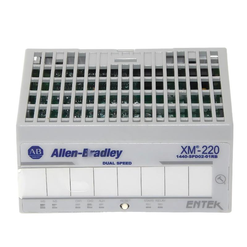
Table of Contents
- Field Case: Compressor Speed Signal Drops During Load Change
- Fault Symptoms of XM-220 Speed Measurement Module
- Observed Speed Signal Fluctuation Patterns
- Root Cause Analysis (Tach Wiring, EMI & Pickup Degradation)
- Diagnostic Workflow for Speed Monitoring System
- Repair & Recovery Actions
- Prevention Strategy for Stable Speed Measurement
- FAQs on 1440-SPD02-01RB Faults
- Engineering Summary
Field Case: Turbine Speed Drop Alarm Without Mechanical Cause
The Allen-Bradley 1440-SPD02-01RB XM-220 speed measurement module is widely used for rotor speed monitoring and overspeed protection. In one turbine application, operators reported intermittent low-speed alarms even though the mechanical speed was stable and verified by handheld tachometer.
Fault Symptoms of XM-220 Speed Measurement Module
Typical field symptoms include:
- Intermittent speed signal loss or dropouts
- False overspeed or underspeed alarms
- Unstable RPM readings under constant load
- Tach input fault or sensor fault diagnostics
Observed Speed Signal Fluctuation Patterns
During field diagnostics, engineers observed inconsistent tach behavior:
CHANNEL_1_SPEED = 2980 RPM (stable)
CHANNEL_2_SPEED = intermittent drop to 0 RPM
TACH_SIGNAL = noisy pulse edges
ALARM_STATUS = intermittent ZERO SPEED / FAULT
PEAK_SPEED = inconsistent reset behavior
The mismatch between channel behavior indicated electrical signal integrity issues rather than mechanical speed variation.
Root Cause Analysis (Tach Wiring, EMI & Pickup Degradation)
The XM-220 module depends on clean pulse signals from tachometers or proximity sensors. Common failure mechanisms include:
- Loose tachometer wiring causing intermittent pulse loss
- Electromagnetic interference from nearby VFD output cables
- Magnetic pickup air gap drift affecting pulse amplitude
- Sensor aging leading to weak or distorted waveform signals
In one field case, rerouting tach wiring away from inverter cables eliminated false zero-speed alarms completely.
Diagnostic Workflow for Speed Monitoring System
A structured signal-level verification process is required:
- Verify tach sensor output waveform with oscilloscope
- Check input voltage range and pulse amplitude stability
- Inspect shielding continuity and grounding strategy
- Compare speed readings between redundant channels
- Test sensor alignment and air gap consistency
SPD_DIAG /MODEL=1440-SPD02-01RB /TACH_VERIFY /SIGNAL_NOISE_CHECK /CHANNEL_COMPARE
Repair & Recovery Actions
- Re-terminated tachometer wiring with shielded cable
- Improved grounding strategy with single-point reference
- Replaced degraded magnetic pickup sensor
- Separated signal wiring from VFD power cables
After correction, speed readings stabilized and false alarms disappeared during continuous turbine operation.
Prevention Strategy for Stable Speed Measurement
- Use shielded twisted-pair cable for all tach inputs
- Maintain proper sensor air gap and mechanical alignment
- Avoid routing signal cables near high-frequency switching devices
- Perform periodic sensor calibration and inspection
- Verify redundancy channel consistency in critical systems
FAQs on 1440-SPD02-01RB Faults
Why does speed drop to zero intermittently?
Because missing tach pulses or noise filtering errors can cause the module to interpret invalid signal intervals as zero speed.
Can one bad sensor affect overspeed protection?
Yes. Faulty or weak tach signals can trigger false protective shutdowns or disable correct speed tracking.
Is the module itself often faulty?
No. Most issues are caused by wiring, EMI interference, or sensor degradation rather than internal module failure.
Engineering Summary
The Allen-Bradley 1440-SPD02-01RB XM-220 speed measurement module provides high-reliability rotor speed monitoring and overspeed protection. Field failures are most commonly caused by tach signal integrity issues, electromagnetic interference, or sensor wear rather than module hardware faults. Proper installation and signal conditioning are critical for accurate speed measurement in industrial rotating equipment.