
NewsNEWCENTER
Featured products
Contact Us
Allen-Bradley 1440-SPD02-01RB XM-220 Speed Measurement Module Installation Guide
2026-06-30
Table of Contents
- Installation Overview of XM-220 Speed Measurement Module
- Role in Turbine & Rotating Machinery Protection System
- Pre-Installation Electrical & Sensor Validation
- Mounting & Control Cabinet Layout
- Tachometer / Proximity Sensor Wiring Rules
- Channel Configuration & Speed Scaling Setup
- Commissioning & Speed Verification Procedure
- FAQs on XM-220 Installation
- Engineering Summary & Field Practice
Installation Overview of XM-220 Speed Measurement Module
The Allen-Bradley 1440-SPD02-01RB XM-220 speed measurement module is designed for high-reliability speed monitoring and overspeed protection in turbines, compressors, pumps, and industrial rotating equipment. It processes pulse signals from tachometers or proximity probes and converts them into real-time RPM values.
Role in Turbine & Rotating Machinery Protection System
The XM-220 module is a critical safety component in machinery protection systems. It ensures accurate speed measurement for alarm generation, trip logic, and overspeed protection coordination with control systems.
Pre-Installation Electrical & Sensor Validation
- Verify 24V DC power supply stability and grounding integrity
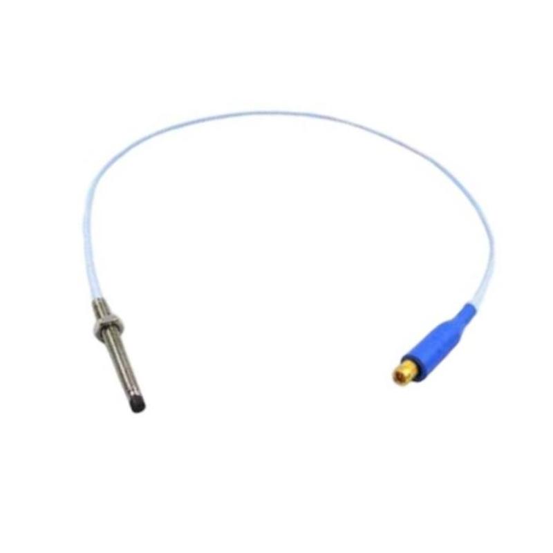
- Confirm tach sensor type (magnetic pickup / proximity probe / encoder)
- Check pulse output amplitude and frequency range compatibility
- Inspect cable shielding continuity before installation
- Ensure correct signal reference grounding strategy
Mounting & Control Cabinet Layout
- Install XM-220 module on DIN rail inside control cabinet
- Maintain separation from VFD and high-power switching devices
- Ensure proper ventilation and thermal spacing
- Avoid routing signal cables parallel to power cables
Field experience shows that improper cabinet layout is a major cause of tach signal instability due to EMI coupling.
Tachometer / Proximity Sensor Wiring Rules
- Use shielded twisted-pair cables for all speed inputs
- Ground cable shield at one end only (control cabinet side)
- Avoid long parallel runs with inverter output cables
- Ensure correct polarity for magnetic pickup sensors
XM220_WIRING_CHECK /MODEL=1440-SPD02-01RB /TACH_INPUT_VERIFY /SHIELD_TEST /SIGNAL_INTEGRITY
Channel Configuration & Speed Scaling Setup
- Define pulse-per-revolution (PPR) value correctly
- Configure RPM scaling based on machine gear ratio
- Set overspeed alarm and trip thresholds
- Enable redundancy channel comparison if required
Incorrect PPR configuration is one of the most common commissioning errors leading to false speed readings.
Commissioning & Speed Verification Procedure
- Start machine at low speed and verify RPM tracking
- Compare module readings with handheld tachometer
- Test overspeed alarm logic under controlled conditions
- Validate signal stability across speed range
- Confirm redundancy channel consistency (if installed)
In one commissioning case, wrong gear ratio entry caused RPM readings to be doubled until corrected during system validation.
FAQs on XM-220 Installation
Can XM-220 work with any tach sensor?
It supports multiple sensor types, but signal compatibility (voltage and frequency) must be verified before commissioning.
Why is shielding so important?
Because speed signals are pulse-based and highly sensitive to EMI noise and false triggering.
Is redundancy required for all applications?
Not always, but it is recommended for critical turbine and compressor protection systems.
Engineering Summary & Field Practice
The Allen-Bradley XM-220 (1440-SPD02-01RB) speed measurement module is a high-precision device used for critical machinery protection. Proper installation requires careful attention to sensor wiring, shielding, configuration parameters, and cabinet layout. Field experience confirms that most speed measurement issues originate from installation and configuration errors rather than module hardware faults.